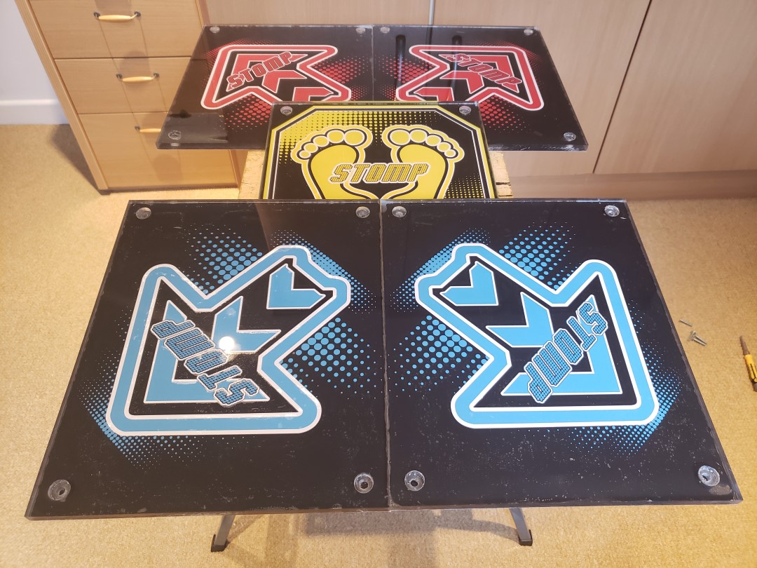
Design, construction and prototypes of the acrylic arrow panels for each pad.
This is the second post in a five part series detailing my process of building a DIY Pump it Up pad. If you don’t know what this is about, check out my project summary here. You can also jump to any part of the series:
- Part 1 - Frame Build and BOM
- Part 2 - Arrow Panels
- Part 3 - Pad Sensors
- Part 4 - LEDs and Electronics
- Part 5 - Arduino Programming
Early design and prototypes
The arrow panels are the equivalent of the buttons on a game controller. It’s what the player uses as input for the game. The original arcade pads use full acrylic panels, I think they are 12mm thick or similar. From the start of the project I knew I was also going to be using full acrylic panels, as I wanted the LEDs shining from underneath.
However, acrylic is very expensive, especially in the thickness required to withstand people jumping up and down on it. I started out with a pad prototype using wood panels instead, which I already had since I used the same plywood as the base of the pad, so it was essentially free. This posed a problem though, as the plywood is 15mm thick and the acrylic would be just 10mm, so I had to design the internal structure of the pad in a way to allow me to easily adapt it to a different thickness, without having to re-build or re-print everything again. After deciding to use plastic for the internal pad structure, I was left with 27mm of height avaiable, which was enough for the 15mm wood panel plus a 12mm sensor, or a 10mm acrylic panel and a 17mm sensor. The obvious choise was to design a 12mm high sensor and just add padding later on.
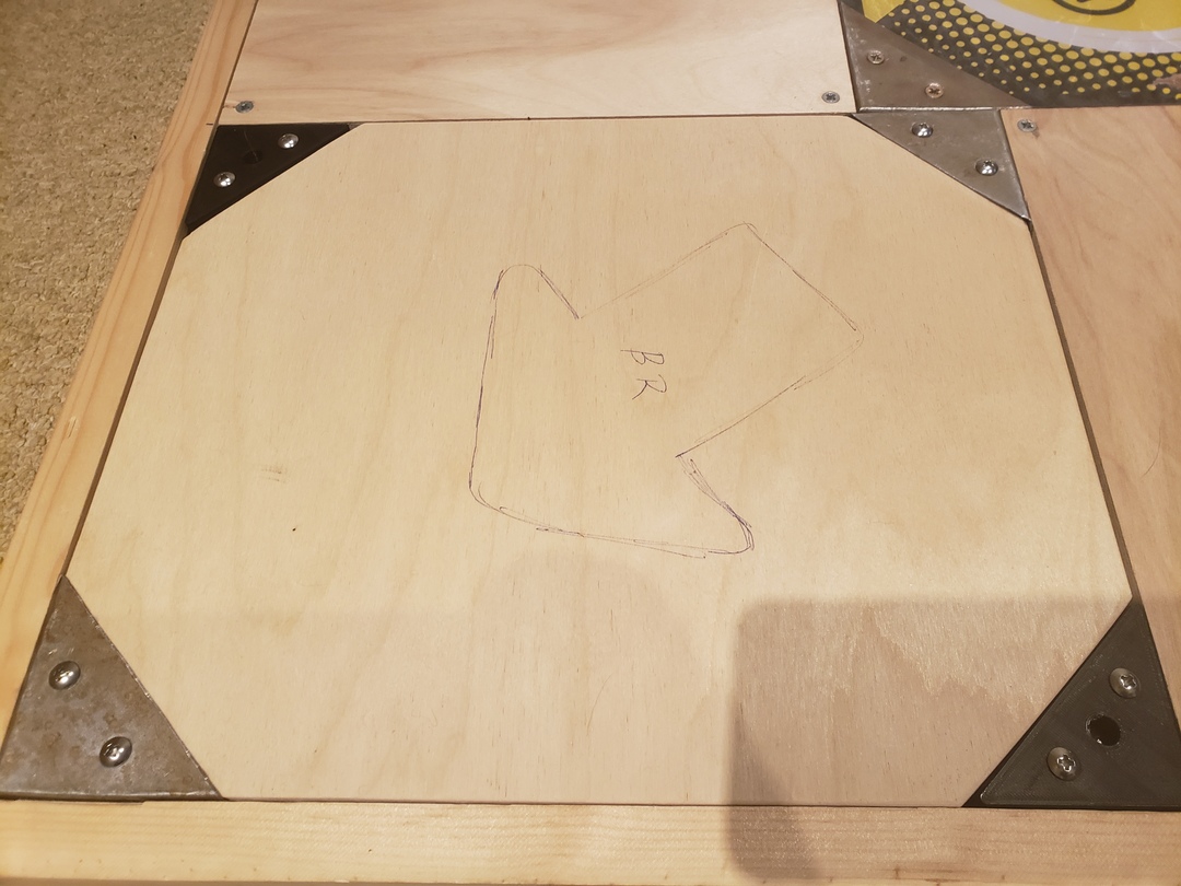
As I said in the previous post, I’ve first built the frame with bracketed arrows, then decided to switch to a bracketless design. I had chosen the brackets mostly for nostalgia, as that’s how the pads were when I used to play it years ago. My DIY brackets, however, were far from perfect, and even after I got some experience in making them, I was never satisfied with how they looked or felt. Because of this, and also because I knew playing on a bracketless pad would be slightly easier, especially when hitting triples, I chose to convert it to the bracketless design. Luckily I made that choice before buying and cutting the corners of the acrylic panels, so I ended up changing both the thickness of the panel (from 15 to 10mm) and their design at the same time.
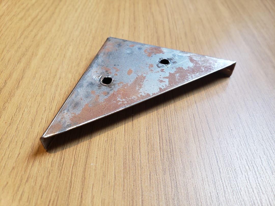
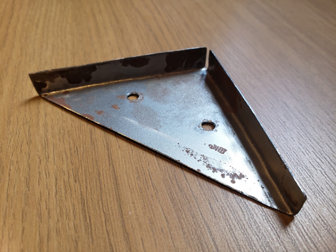
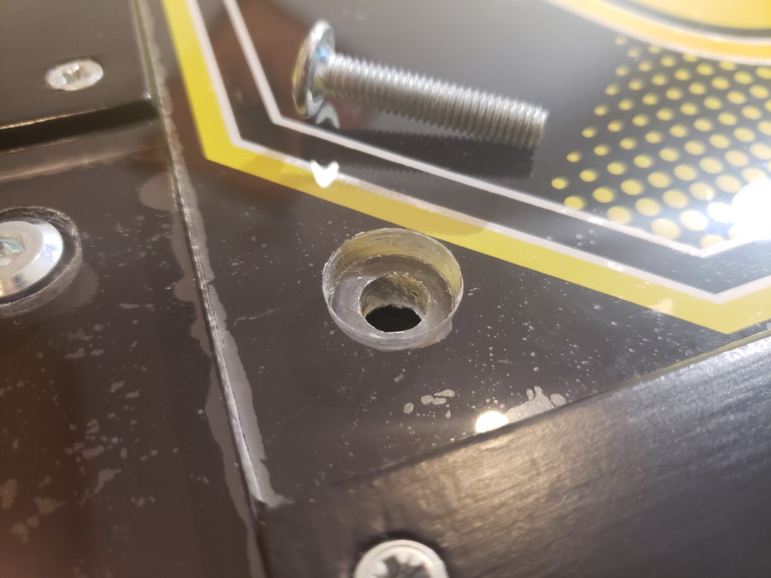
The brackets did serve a purpose though, which was to hold the acrylic panels in place. Otherwise, when you step in the corner of a panel, the opposing corner would lift up, potentially lifting the whole pad out of its place, ruining the song, and potentially hurting your feet. The bracketless panels also need to have such restraints, so after researching how the original pads work, I decided to drill a 2-step hole on each corner, to allow the screw to sit completely flush so it doesn’t catch the player’s feet, and also to secure it so it doesn’t fly away. The centre of the hole is located 20mm away from each edge, with the smaller hole (for the screw to pass through) measuring 8mm in diameter, and the larger hole for the screw head measuring 15mm in diameter. The screw itself is an M6 screw (6mm diam) with a head that measures 12.5-13mm. The extra millimeters are meant as slack so the panels can move a bit and not get caught in anything to avoid them sticking. In reality, a few of the smaller holes had to be enlarged to 10mm because of misalignments.
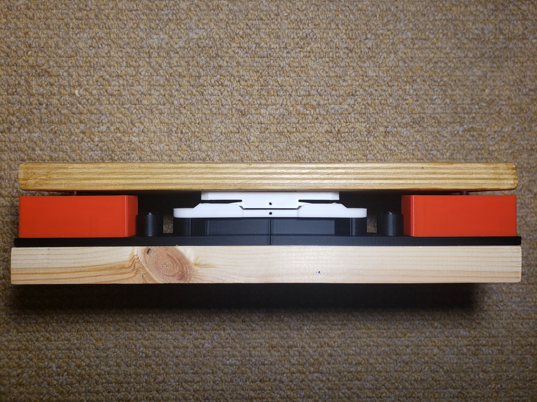
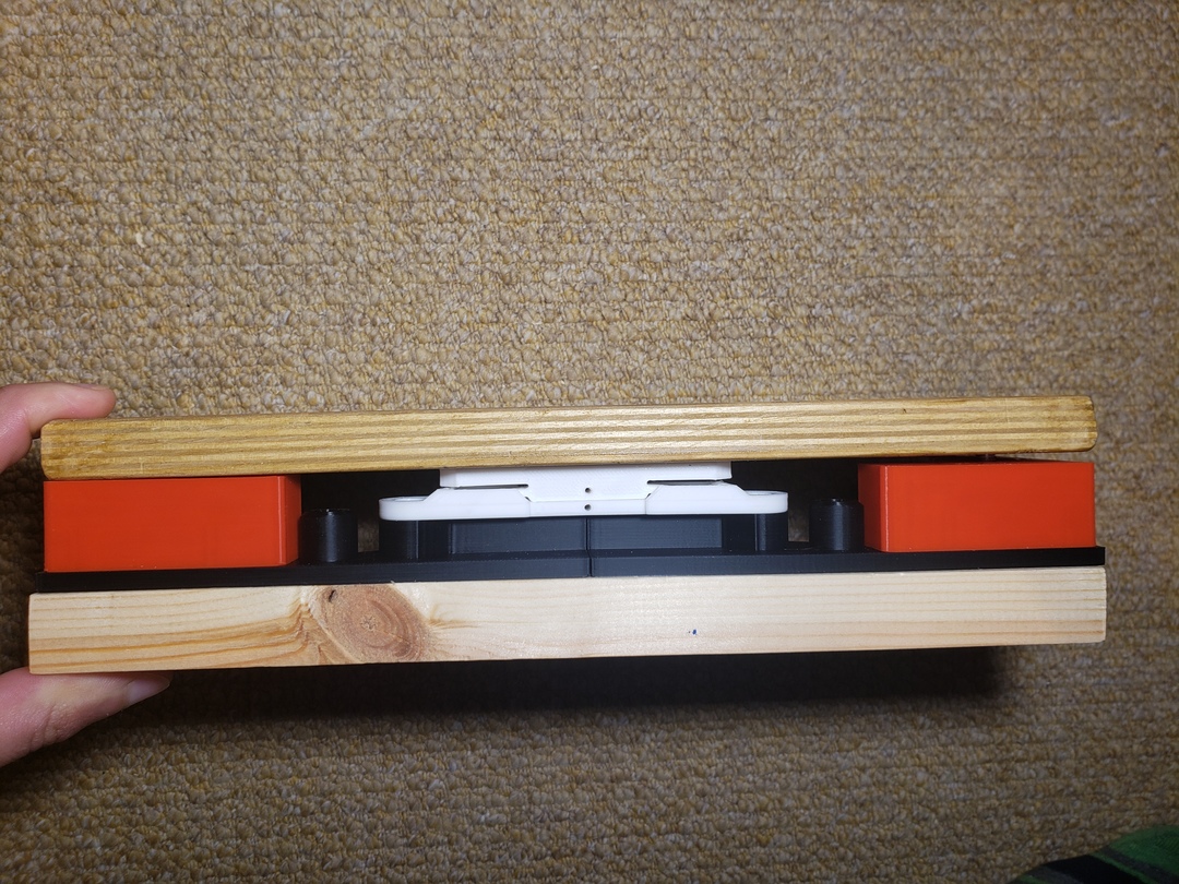
Before commiting to the bracketless design, I decided to first test the screw mounts and how they would interact with the sensors. To do this, I’ve build a test module, which ended up being an almost perfect cross section of the entire panel frame. This included the base of the frame, panel frame, sensor, panel, and the screws on top. While I did have to modify the design to work with the 15mm plywood, it served its purpose, validating the design and providing a nice visual feedback on how the sensor works when stepping on different areas of the panel.
Build
The acrylic (actually polycarbonate) sheets were ordered to size, so I only needed to drill the screw holes and stick the noteskins on them. Drilling those holes had to be as precise as possible, but I don’t have a vertical drill stand or a drill press, and I knew that if I tried to do it fully by hand, the holes would not align properly with the 3D printed frame below. To avoid this, I designed and 3D printed a jig to correctly place and align the drill on the holes, and used a strap clamp along with some earlier failed jig prototypes to secure and align the jig with the panel, as seen below:
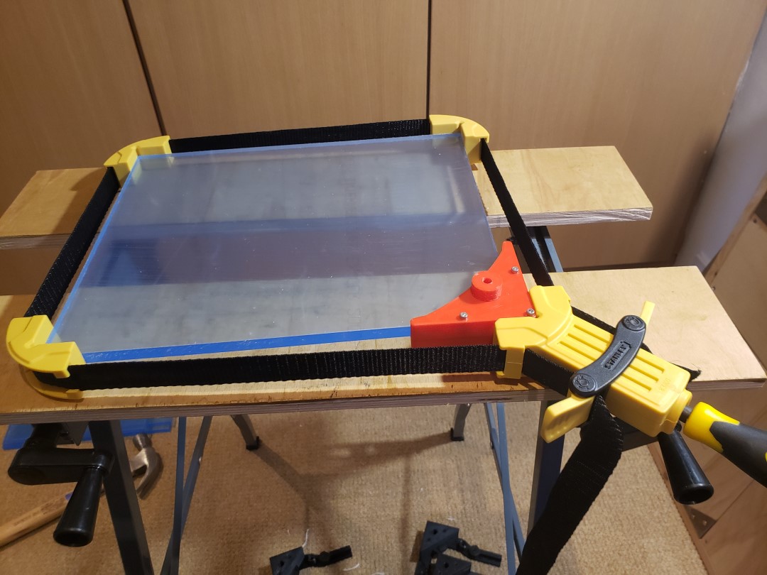
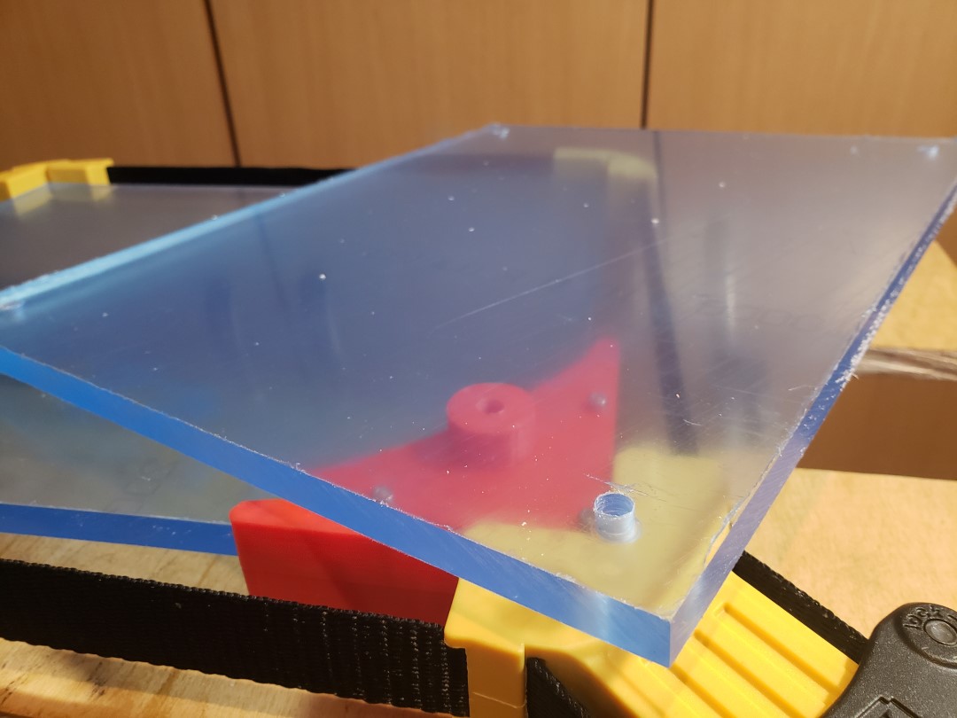
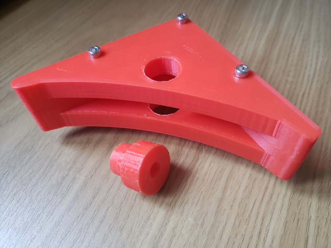
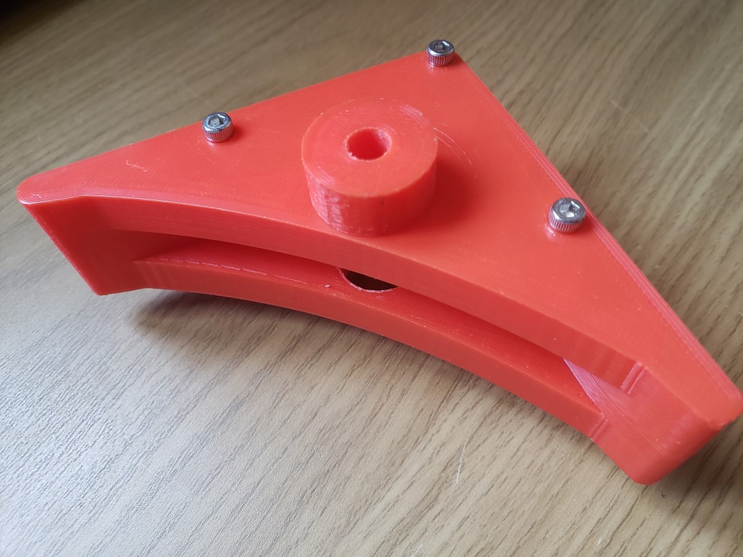
The jig had three parts: two identical but mirrored parts that were screwed together, and left a gap of exactly 10mm so the acrylic panel could slide into it. This main “body” part had a 15mm hole meant to align the 15mm drillbit for the screw head hole. A third part was a guide for a 6mm drillbit, which would fit into the 15mm opening to perfectly align the two holes with one another. Because these were made out of plastic, the alignment was never perfect, as the drill would chip away the plastic when I accidentally tilted it, and in the end the 6mm hole ended up being probably closer to 7mm. After drilling the 6mm hole, I removed the small 6mm guide and drilled roughtly 2 to 3mm deep with the 15mm drillbit. After all four corners were finished, I then got some calipers and used them to drill a 15mm hole that was precisely 4.25mm deep. This depth was so the corners would lift just enough to allow the opposite corner to register a step correctly, while keeping the screw flush even when the corner was fully pressed. After this, I used an 8mm drillbit (without any jigs) to enlarge the 6mm hole into 8mm one. I did this as I initially thought 6mm would be enough, but because of misalignments I had to enlarge to 8mm and didn’t want to print the jig again.
Noteskins
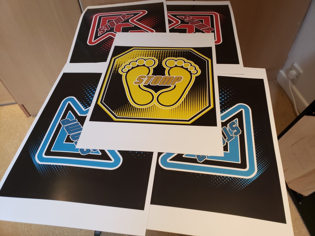
For the panel art, aka noteskin, I got the official designs online then tried printing them on my home inkjet printer in 2 A4 sheets, which I then glued onto the acrylic. This more or less worked, but was imperfect because one could easily see the seam where the sheets meet, and the cheap office paper texture was also very noticeable. Even so, it was good enough for me, and I was ready to commit to that. Unfortunately, the printer ran out of black ink, and in a bizzare twist, I found out that basically the whole of Europe ran out of my specific HP ink cartridge, because of the COVID-19 pandemic.
After looking everywhere for the cartridge, I just decided to have it printed in a more professional paper straight in a A3 sheet, which wouldn’t have any seams. This was better in many ways to my homemade printing, but it lacks in one aspect: I used white glue to glue the paper with the acrylic, and while that worked incredbly well for office A4 paper, it doesn’t stick as well for semi gloss paper, so the edges of the panels are lifting a bit and I feel that the points where the panels contact the sensors will also lift and be ruined soon. I did order 2 copies of each noteskin, so I have one complete set here that I’ll eventually replace when I buy a suitable adhesive for it.
