Details about how I initially designed and built the hybrid wooden + plastic frame. This also includes the complete Bill of Materials (BOM) for the entire pad, with all associated costs.
This is the first post in a five part series detailing my process of building a DIY Pump it Up pad. If you don’t know what this is about, check out my project summary here. You can also jump to any part of the series:
- Part 1 - Frame Build and BOM
- Part 2 - Arrow Panels
- Part 3 - Pad Sensors
- Part 4 - LEDs and Electronics
- Part 5 - Arduino Programming
Project
My initial idea for this project was to build a sturdy wood and metal frame, identical to the arcade ones, both in size and in looks. I then started to google the exact dimensions and specifications for the panels, how the sensors worked, etc. With that in hand, I started to design a wooden frame in Fusion 360. At first I had only a rough idea of the size of the timber I was going to build, so I made sure to parameterise everything so that I could adjust in the future. I designed it so it would need as few and simple cuts of wood as possible, because I don’t have a decent power saw, and little practical woodworking experience.
From the beginning I knew I was going to build this using an iterative design process. The design of the frame and the whole pad changed and evolved many times, during design, build, and even after I had a working pad. The first big change was the decision to use 3D printed parts for the brackets supports, instead of cutting wood triangles. After that, I noticed that the plastic was really sturdy, so eventually I decided to get rid of almost all internal wood bits and use a 3D printed support frame for each arrow panel as well. The last major change was to get rid of the brackets and build a bracketless pad, as that’s what the arcade pads use in the newer machines. The first complete version of the pad was fully bracketed, so I devised a way to migrate this to a bracketless design using the same parts as before.
After finishing an initial version of the pad, still using wood arrow panels instead of acrylic ones, I got one acrylic panel made so I could test how the acrylic would behave, as I wasn’t quite sure it could take on the weight and impact, but it turns out that it can handle those pretty well.
After playing for a while I started having some issues with the sensors and had to re-design them, leading to a need for more vertical space inside the pad. The wood structure frame for the arrows took 20mm of the internal available height (a total of 42mm), and the wood arrows I was initially using were made from the same 15mm plywood sheet as the frame. This forced the sensors to have a maximum of 7mm in height, which was not enough and was the reason I had problems in the first place. I then ended up having to design a shorter support frame for the arrows, which is why I made the move to the internal 3D printed frame. I ended up with a structure that allowed the sensors to be 5mm higher than before with wood arrows, at 12mm height, which was enough to design decent sensors.
You can view and download the Fusion360 design, and all 3D printed parts, in either Thingiverse or PrusaPrinters:
- https://www.thingiverse.com/thing:4437046
- https://www.prusaprinters.org/prints/33072-pump-it-up-dance-pad-printed-parts
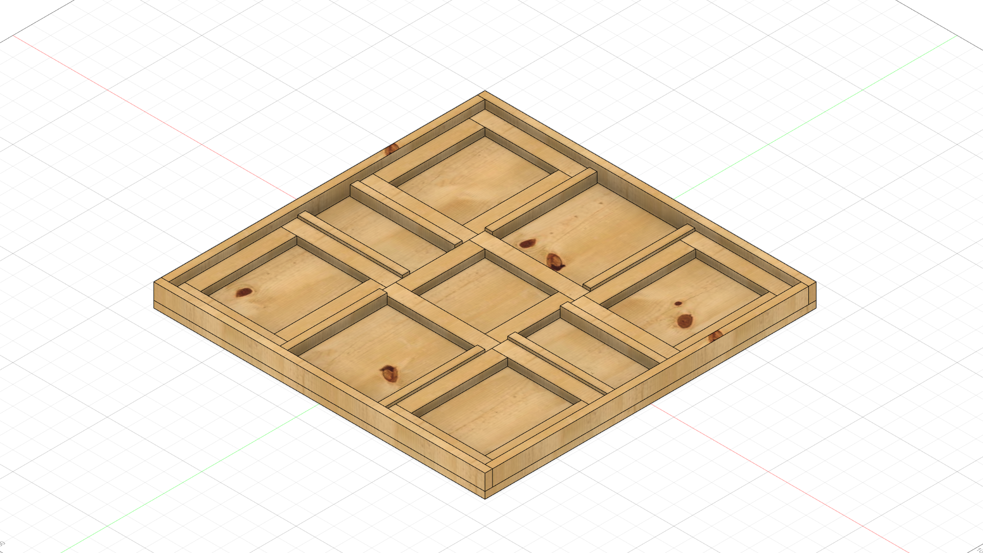
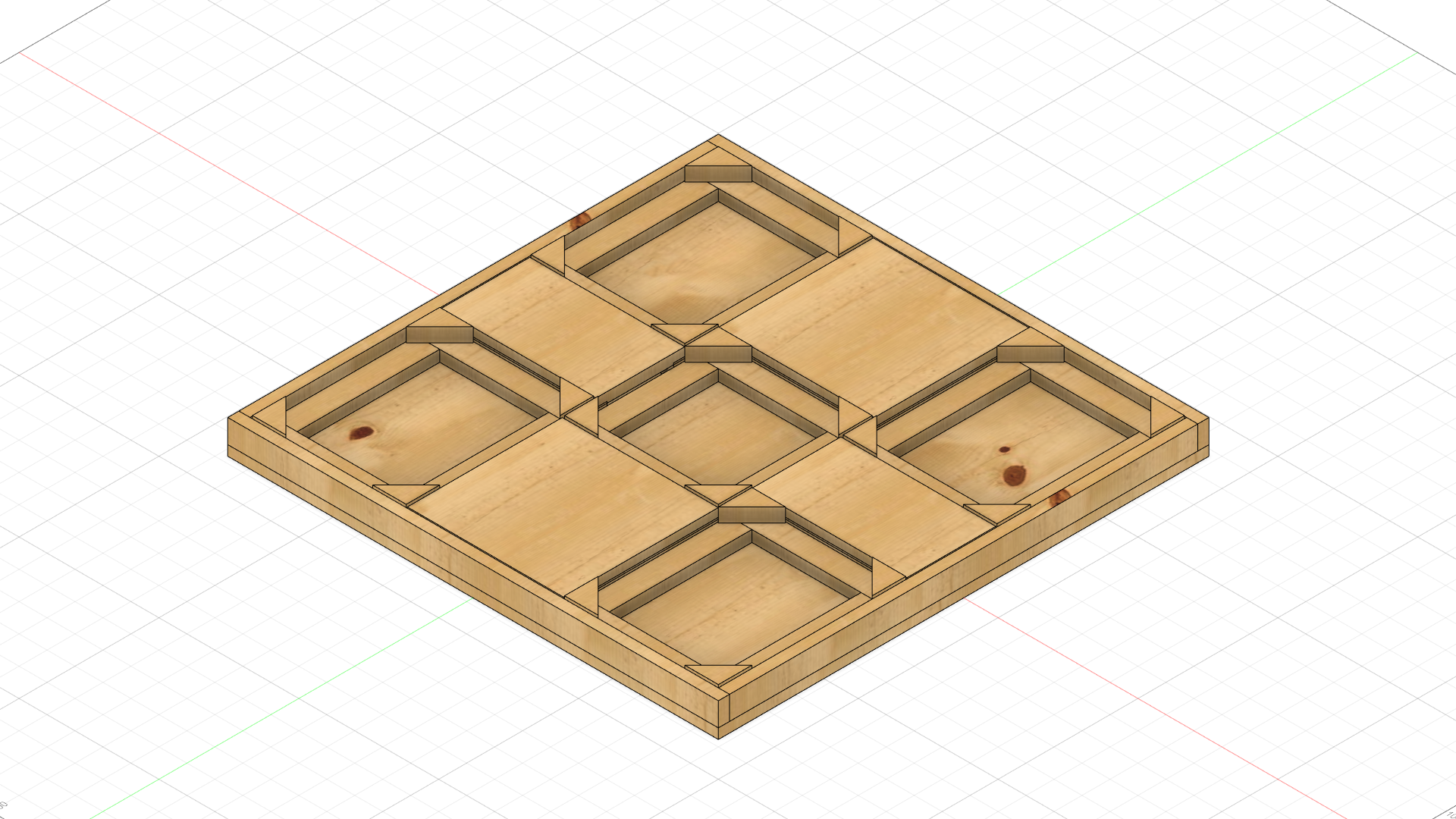
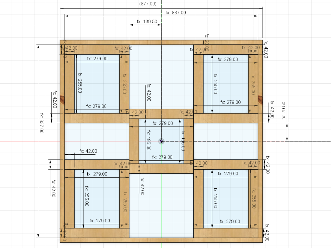
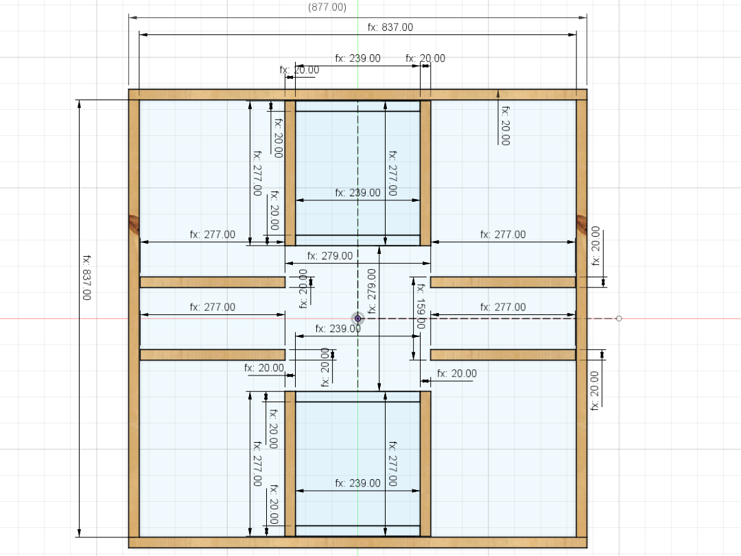
The following images are from the initial Fusion 360 design I made, which is also available in the links above. All the dimensions are correct for the finished pad but, on the bottom left picture, those timber pieces were replaced with 3D printed parts. Also note that the design is for an old-style bracketed pad, so it includes measurements for the brackets, but those can just be ignored.
Sourcing the materials
I then started looking for a local steel supplier to get the metal plates for that nice quality finish. After getting a few quotes, I quickly realised that the metal plates would be by far the most expensive part of the project, as I’d need to get them already cut and bent, as I don’t have the necessary tools (a press brake) to do so. Even without that, the cheapest quote I got was around €120, and that didn’t even include the bending, so I simply gave up on using metal.
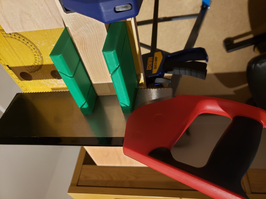
As for the wood for the frame, I managed to find a place that sold the plywood sheet already cut to size (at a small premium), which saved me a lot of work. To cut the 42x20mm (equivalent to 2x1”) timber, I used a mitre saw and a 3D printed mitre block. Throughout this project, I used a few 3D printed tools and jigs too (did I mention I love 3D printing?), making some of the processes easier and more precise.
All those 3D printed parts amounted to quite a lot of plastic I had to use. I printed all the jigs with leftover filament in random colours, but I wanted the plastic frame to be of the same colour as the wood frame (black), and I also wanted the sensors to all have the same colour as one another. I bought 2 rolls of 1kg filament for this, and used up most of them both.
Build
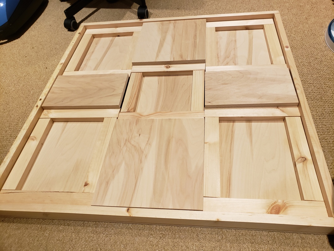
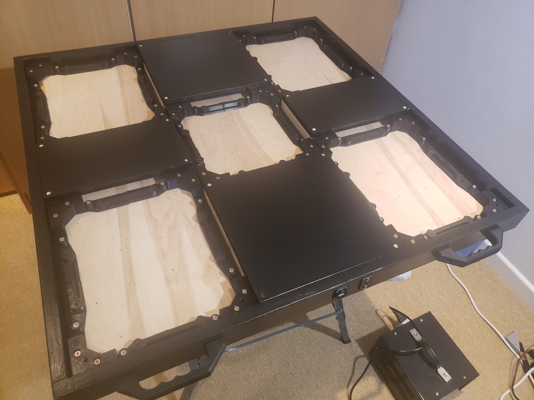
After cutting all the timber to size, I was ready to assemble the first version of the frame. As mentioned before, this would not be the final version of it, as I replaced all the frame structures for each arrow panel with 3D printed ones. To assemble and secure the frame, I used 4x30mm wood screws. I also used wood glue to fix the frame’s outer walls with its base, as those were the only parts I knew for sure I wouldn’t need to disassemble or change later. I’m glad I only glued that, otherwise I wouldn’t be able to use the plastic parts later on. Below is a photo of that first, all-wood frame, just prior to me fixing and gluing everything in place, side by side with a photo of the final hybrid finished frame, without the sensors and electronics.
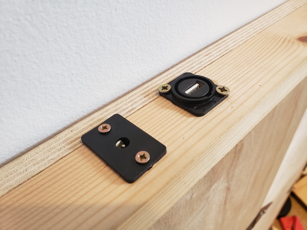
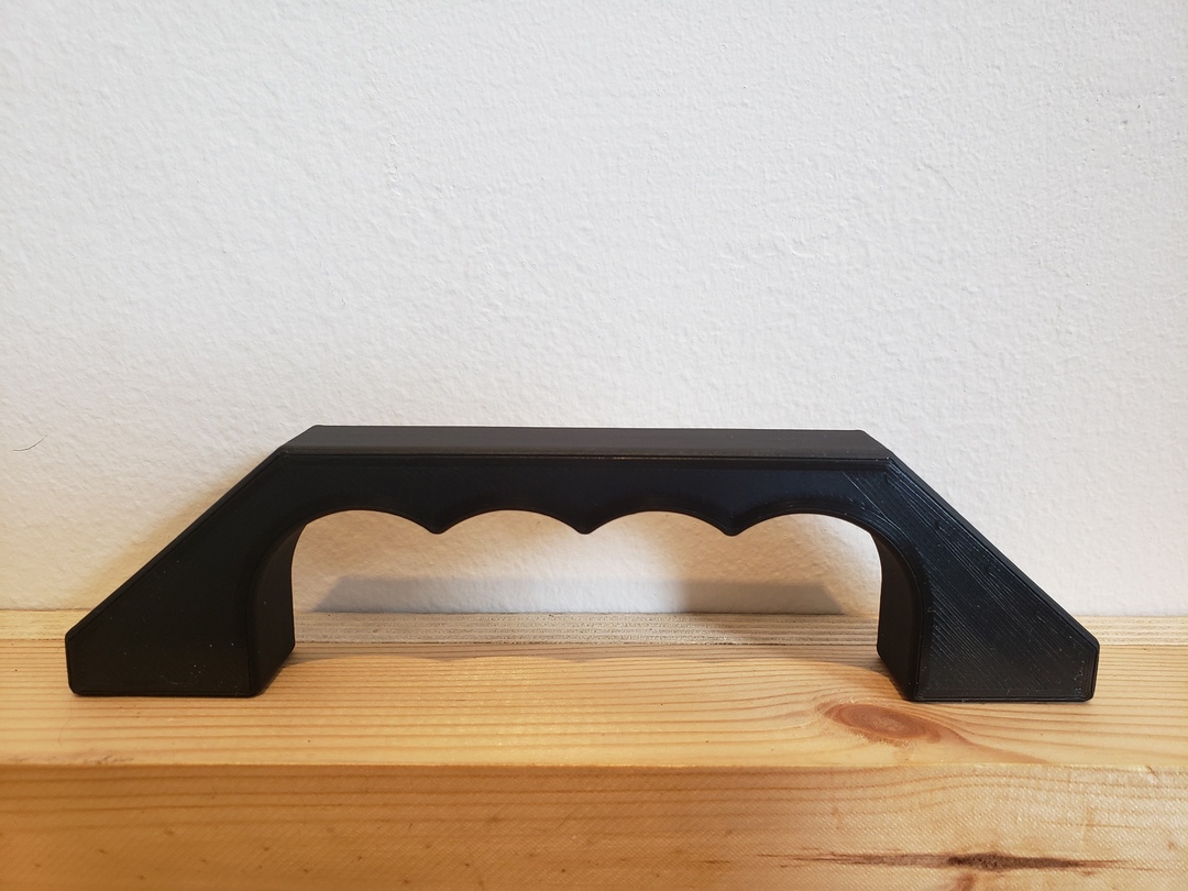
Lastly, I decided to incorporate a USB socket to facilitate plugging the pad into a computer, to avoid having a fixed, dangling cable while the pad was not in use. The photo below also shows a second socket, a generic DC power socket. This was meant to be used as a power source input for the LEDs, but ultimately I scaled down on the number of LEDs and the current draw fell to whithin the limits of a USB 3.0 connection, so that’s not needed for now. Two handles were also designed and 3D printed so I could easily lift the pad from the floor and carry it around to store it while not in use.
Painting
As I said, the initial idea was to have metal plates all over the pad, to hide the wood, but for budgetary reasons that never happened. I didn’t want to leave the pad without any finish, so I decided to paint it a satin black to make a sort of stealthy look with the arrow panels kind of merging into the frame.
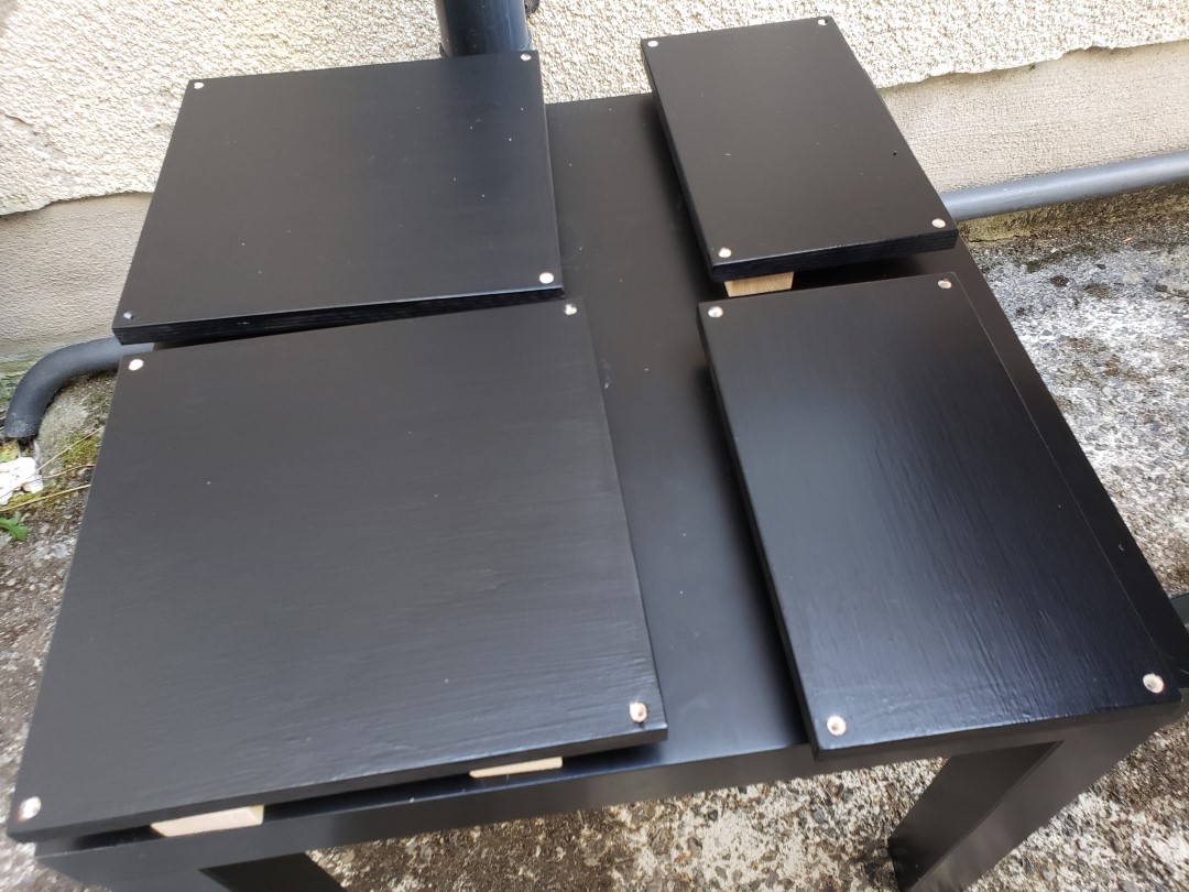
Before painting, I disassembled the whole pad, took everything off down to the last screw, sanded down all the four plates between the arrows, and the frame (which was just the ply base and the external walls glued together) with 220 grit sandpaper with a detail sander (a random orbit sander would be better, but I don’t have that). Worth noting that I also lightly sanded the paint down too before applying the varnish, but as the pictures show, it didn’t improve much of the surface finish, and the whole paint job is not very good (if I could either program or 3D print the paint I would).
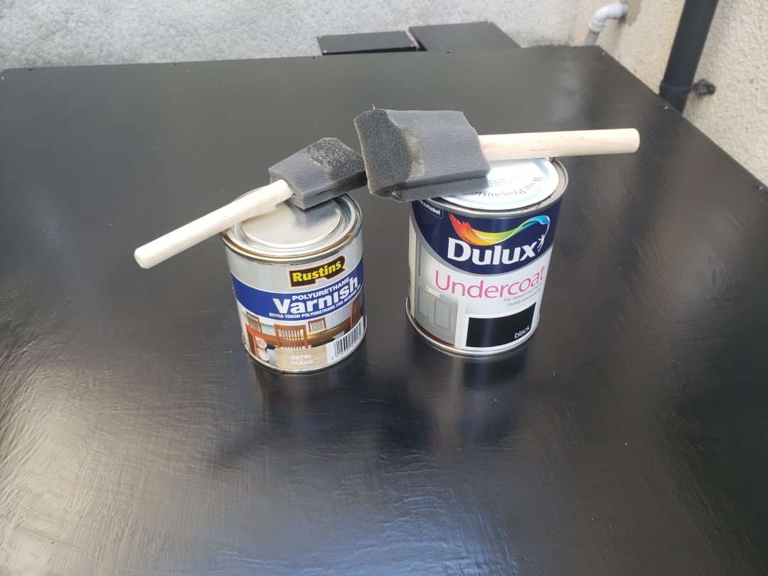
I used a black undercoat paint, a sort of 2-in-1 primer + paint, and a polyurethane varnish to protect it. Both were oil-based, so they smelled terrible and took a very long time to dry. I ended up having to do this outside as I was starting to get headaches after I painted just a small test timber piece inside. I would apply a coat of paint/varnish in the morning and leave it outside to dry until sunset, then I would bring it inside for the night, and the next day I’d either repeat that or just leave it all day to dry. It took me 2 coats of undercoat, 2 coats of varnish and 6 days to finish this part, plus another 4 or 5 days inside waiting for the frame to dry to make sure the varnish was dry enough so I wouldn’t damage it. After that I assembled it all again and it was finally finished.
Bill of Materials for the pad
These are the materials and parts I used to build the whole pad, along with approximate costs for each. I already had some of the electronics and 3D filament, so some prices are based on what I could find online at the time of writing. The estimates are only for the finished pad, in reality I’ve probably spent almost double of what’s here due to all the changes, prototypes and redos I had to do along the way.
The 3D printed parts were all printed with 3 perimeters and between 10-20% infill. Using a denser infill was not really needed because the number of perimeters and screws used (it uses a total of 179 screws!!!) gave the parts more than enough strength. Most parts were printed in PLA, with a few printed in some leftover ABS I had laying around. So far, after a few months of use, none of the plastic pieces show any sign of wear, but only time will tell if and how much deformation creep will affect it.
Note that some of these materials come in larger packages where only a fraction of them was used (for instance, the paint and varnish could be used for a second and maybe even a third pad), so the cost for building two pads should be lower than simply doubling the cost for a single one, especially when you consider shipping costs which are not included at all here.
Tools:
I’m not including the cost of the tools, as I already owned some of them, but I wanted to list them anyway:
- DeWalt 650W corded impact drill (used as a drill and as a power screwdriver)
- Makita Detail Sander
- 3D printer (Prusa i3 clone)
- Foldable workbench
- Mitre saw
- 3D printed mitre block
- 3D jigs for cuts and holes
- Wood adhesive
- Foam brushes
- Dremel
Materials:
| Material | Quantity | Unit price | Total price |
|---|---|---|---|
| 15mm plywood sheet, 1550x1500mm cut to size | 1 | €39.50 | €39.50 |
| 42x20mm treated timber, 2400mm long | 3 | €2.93 | €8.79 |
| Spax wood screws 4x30mm box of 200 | 1 | €4.99 | €4.99 |
| "Furniture" M6x30mm wide head screws | 20 | €0.30 | €6.00 |
| Dulux Undercoat Black 750ml | 1 | €18.95 | €18.95 |
| Rustins Polyurethane Varnish Satin Clear 500ml | 1 | €7.99 | €7.99 |
| Black PLA filament 1kg | 2 | €20 | €40 |
| Metal USB socket female to female | 1 | €2.35 | €2.35 |
| 10mm clear polycarbonate pads cut to size | 5 | €15.00 | €75.00 |
| WS2812B LED strip (min. of 40 LEDs needed) | 1 | €15.00 | €15.00 |
| Arduino Leonardo | 1 | €8.75 | €8.75 |
| Electrical wires (between 18-22AWG) | ~5m | €1.00 | €5.00 |
| JST RCY connector pair | 20 | €0.10 | €2.00 |
| Protoboard PCBs | 5 | €0.074 | €0.37 |
| Conductive copper tape (slug tape) | 1 | €4.99 | €4.99 |
| USB Cable A to micro B 20cm | 1 | €3.99 | €3.99 |
| USB Cable A to A 150cm | 1 | €5.99 | €5.99 |
| Printed A3 arrow panels art | 5 | €5.00 | €5.00 |
| Total cost | €254.66 | ||
Plywood and timber measurements:
These are the sizes in which the plywood and timber need to be cut, for a hybrid wood/plastic pad using 42x20mm timber and 15mm plywood:
Plywood for the plates between the step panels:
- 1x 877x877mm (base)
- 2x 277x159mm (left and right plates)
- 2x 277x279mm (up and down plates)
Acrylic/Plywood for the step panels:
- 4x 277x337mm (corner arrows)
- 1x 277x277mm (center step)
Timber for the frame walls:
- 2x 877mm
- 2x 837mm
- 8x 277mm*
* These last 8 cuts need to be trimmed down, so the timber measures 27x20mm instead of 42x20mm. The 27mm size is basically the difference between the large side of the timber (42mm) and the thickness of the plywood (15mm). It’s sized so the plywood platforms will remain flush with the pad walls.