Guide on how to program a generic HID game controller with Arduino, and how to control LEDs on the pad.
This is the fifth and last post in a five part series detailing my process of building a DIY Pump it Up pad. If you don’t know what this is about, check out my project summary here. You can also jump to any part of the series:
- Part 1 - Frame Build and BOM
- Part 2 - Arrow Panels
- Part 3 - Pad Sensors
- Part 4 - LEDs and Electronics
- Part 5 - Arduino Programming
Disclaimer
I’ve decided to write this post a bit differently from the other posts in the series. Why? Because I feel that this may be useful as a starting guide for any type of Arduino-based game controller, not just a PIU pad. Therefore, I’ll explain step by step the parts of the code that are responsible for each feature needed for a game controller in a more generic way, then I’ll focus on aspects that are exclusive to my PIU pad.
There are 5 steps on this guide, and for each step, there’s a file in the repo with the relevant code. There’ll be links for that on every step. This post is also filled with embedded Github gists, so there should be a lot of code in here. If for any reason that doesn’t render, something is wrong, so please let me know.
PIU controller code
But first of all, if you just want the code for a PIU/DDR pad, here it is. This controller is meant to be used with a dance game pad, like PIU or DDR (can be used in both):
https://github.com/roooodcastro/dance_pad_controller
I’ll quickly go over how to use that. Instead of having a single file as it’s usual with Arduino projects, I decided
to split them up into C++ style files (header and cpp files). Because the code is quite complex and extensive, this
makes it much easier to concentrate all configuration needed into one place and hide the complexity away. If you’re
building a PIU pad that’s remotely similar to mine, I believe you’ll only need to edit the configuration.h and
mappings.h files.
Those two files hold all major configuration values, and for each value there are comments describing what they do and how and when to change them. The repository’s README also has further explanations on how the program works.Hopefully that’s all one would need to use the code, but feel free to complain if something is too confusing or it doesn’t do everything you need.
Step 1: Emulating a HID device
Some versions of Arduino have built-in USB connection, integrated within the ATmega processor itself. This gives them
the ability of appearing to a connected computer as if it was a native keyboard, mouse or a game controller. These are
called HID, short for Human Interface Device. Any Arduino board that uses the ATmega32U4 processor can act as a HID.
You can check a list of all Arduino boards here, the main ones which are
HID-compliant are:
- Arduino Micro
- Arduino Leonardo (the one I’m using)
- Arduino Yún
- Arduino Esplora (which is already a game controller in itself)
In order to get the Arduino to emulate a HID device, we could use the native libraries Keyboard or Mouse. This, however, would result in the pad typing out random characters as the player plays the game, or clicking when it shouldn’t, which is probable not correct in most circunstances. Instead, we’re going to use the ArduinoJoystickLibrary by MHeironimus. It’s a third party library, so it must first be installed. This can easily be done by following the installation instructions in the repo.
The library can be initialized like so:
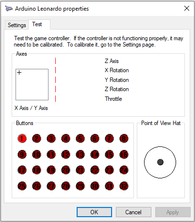
This will create a Generic Game Controller device on PC, but as we’re not specifying how many buttons it has, or if it has hat switches, analog axis, etc, it will come with all bells and whistles by default. For a dance pad we only need 5 buttons, so we can change the initialization code to reflect that:
This will result in the following controllers being created in Windows. Note that the first button is pressed,
because that’s what we told it to do with Joystick.setButton(0, true):
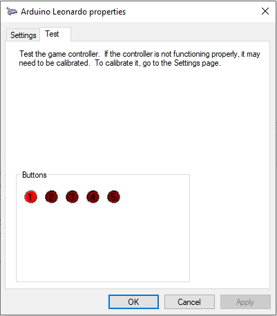
You will notice that Windows labels the pressed button as button 1, while the code is telling button 0 to get pressed. This is because in code, the buttons are zero-indexed, which means they count up from 0, instead of 1. Also, the controller will show up with the name “Arduino Leonardo” (if using Leonardo). This name is not meant to be changed, but you can trick your computer to change the display name for your Arduino board. This will only work on the Windows PC that you configured, if you plug the device on any other computer it will show up as “Arduino Leonardo” again. To properly change this name you’d need to apply for a new USB Vendor ID, which is actually very cheap and accessible at just $5,000/year :)))
Lastly, for a more complete visualization of how we can control these buttons with Arduino, the following code loops through these five buttons, switching them all on and off in sequence. Try uploading this code to a HID-compliant Arduino to see it in action:
Step 2: Setting up the input pins and reading data from buttons
Now that we can emulate a Joystick and send button presses to a PC, let’s actually read data from the controller so we
have something meaningful to send. For buttons we want to use Arduino’s digital pins. These pins can be used as both
input and output, so we have to specify the mode for the pins we want to use. There are three modes for digital pins:
INPUT, OUTPUT, and INPUT_PULLUP. We’ll be using the latter, INPUT_PULLUP. A
pull-up is the name given to a resistor that’s placed between the
Vcc pin (voltage source) and the button. It ensures that the button will always have a well-defined state. Arduino is
nice enough to implement this for us, so we don’t need to use external resistors. If your button already has a pull-up,
you can just use INPUT instead.
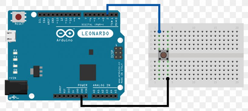
This is how we can read input from the buttons with Arduino and send it to the PC. Adjust the pin numbers as necessary according to how your Arduino is wired up:
Step 3: Input debouncing
The code above might be enough for some games, but for others, especially when press timing is relevant, we need to fine tune the press detection a bit. This also depends on the physical switch you’re using as a button too, there are some precise buttons out there, but most will have the following behaviour when you press them: After you apply force to press the button, the electrical contacts will close, but because all materials have some degree of elasticity, the button might momentarily jump up a bit, making the contacts open again for a fraction of time before they close again for good while you’re pressing it down. This will result in two very fast button presses to be sent to the PC, and for some games this will lead to unexpected and usually bad behaviour.
This issue is called “Switch Bounce”, or “Input Bounce”, and to fix it we must implement debouncing. This is a pretty straightforward algorithm that limits the number of times the button can switch states in a certain amount of time. We can configure this to a time interval such as 40 milliseconds, which is fast enough to allow up to 25 state changes per second, but slow enough to filter almost all bounce issues. You can adjust this to lower values if your sensors are more precise, or higher values if your sensors exhibit bouncing, or flickering issues. It works like this:
So basically the code stores two values for the button: its known state in buttonPressed, and the timestamp when it
last changed state, in lastChangeTimestamp. It uses that timestamp to know if the button can change state again. If
that interval is still within the debounce window, the button can switch on an off a million times, it doesn’t matter,
its “true” state will not change, and that’s exactly what we want.
The following is the full debounced code for all five buttons. Note that the code is very long and repetitive now. This will be addressed in the next step.
Step 4: Refactoring and code “beautification”
At this point the code has 145 LOC (lines of code), which is a lot for something that just reads button presses and passes that on to a computer. In my final solution I split the code into several different files, each with its own unique responsibility. This makes it easier to read and maintan later on. The debounce code can be improved with the use of arrays to store the information we need. This allows us to iterate over the buttons and dynamically read the inputs.
And just like that, 145 lines turned into 65, a reduction of 55% lines, not bad. The NUMBER_OF_BUTTONS macro now
controls how many buttons we will set up and read. The only thing that needs to be done outside the loop is to tell
the program which pins correspond to which buttons.
This concludes the basic Arduino game controller guide. As this is part of a series on Pump it Up dance pads, I will not cover other types of inputs, such as a hat switch, or analog switches like accelerator and brakes. The next section will shift the focus back to the PIU pad.
PIU pad: LED control
Coming back to the PIU pad, the LED strip used, WS2812B, is an addressable LED strip. This means that each LED can be controlled individually. This is great as it allows us to set different colours to different LEDs in the same segment. This can be very useful if you decide to wire the LEDs of all five pads as a daisy chain, because this means you’ll only need one single digital pin on the Arduino to control the LEDs for the entire pad. This is not the approach I took however, as that required more complex wiring, and I wanted to keep the wiring as simple as possible.
Even though we’re not really going to use the “individually addressable” feature of the strip, we’ll still only need one pin for each arrow, meaning 5 digital pins in total to control the LEDs. If we were using a non-addressable strip, we’d need one digital PWM pin (which is a special type of pin on Arduino) for each colour of the strip (or just one for non-RGB strips). On top of that, a MOSFET transistor would also be required to supply the power to the strip.

LED Arduino Library
To control an addressable LED strip we ned to use a compatible LED library. For WS2812B (and many others) there’s a
third party library called FastLED. It also required installation, but unlike
the joystick library, this one can be installed directly from Arduino IDE. Just go to Tools > Manage Libraries... and
search for “FastLED” (by Daniel Garcia). This library is great because it supports a good range of different LED
strips, here’s a list of supported LED chipsets. This is
how a LED strip of 8 LEDs can be set up with the library:
This example is good for showing the most basic example of LED control, but it’s really boring visually. Try making
these changes to the for loop inside the loop() function for something more fun:
Colour selection
Depending on the transparency and print quality of your arrow pad, just using a white strip might wash out the colour of the panel art, making it look more white than anything. To avoid this, I recommend using a RGB strip and using a slightly tinted colour for each arrow. As I mentioned on the last post, different colours draw a (slightly) different amount of current. Also, if you’re using USB-only power, you’ll probably need to decrease the brightness so your USB port doesn’t burn up.
There are two ways of defining colours in this library: RGB or HSV colour space. Using HSV you define a hue value (the colour itself), saturation (how vivid or washed off the colour is), and the brightness. As you can see, you can directly control the brightness levels when using HSV. RGB, on the other hand, requires you to specify values for each colour component (red, green, blue). At the end of the day it’s a matter of personal preference, as HSV will be converted to RGB anyway.
This next code snippet shows how to use HSV colours in FastLED. Note how you can set a CRGB variable with a CHSV
value. This is very handy as you can sort of mix and match between the two when defining colours. Also included here
is a new function to set the colour for the strip, looping over all LEDs and calling FastLED.show() at the end:
Power requirements
To calculate current draw, you can hook up an ammeter to the strip and test various colours, just remember there are five arrows to supply power to. If you don’t have an ammeter or multimeter, you can roughly calculate the current for a WS2812B strip by assuming that each colour draws a maximum of 15mA when its RGB colour value is 255, the maximum. As I said in the previous post, each colour draws a slightly different amount of current, but the difference is small enough that it doesn’t make a huge difference in the end, you won’t set your computer on fire because you calculated for red but green draws an extra 1mA.
So doing this, each LED will draw up to 45mA, since it has three colours. If you want half power, for instance, you
can only take 22.5mA per LED, so you can either split it equally, giving 7.5mA to each colour, which will result in a
RGB value of (128, 128, 128), or you can do as I did and use more red for the top arrows (which are red), more blue
for the bottom arrows and more yellow (red+green) for the centre step. So instead of giving each colour 7.5mA, you can
put 11.25mA for blue, and just 5.625mA for the other two. It will still add up to 22.5mA, but you’ll have a blueish
colour. This looks like (96, 96, 192) in RGB by the way. Of course you can also have a pure blue or red colour, but
I found that to be too overpowering and very obvious that the colour was coming from the LEDs instead of the panel art
itself.
In terms of LED colours and brightness, I really recomment that you experiment with the colours in your pad to see
what looks best. My dance_mat_controller code already has the colours I used in it, the colours I’m using use 66%
of the full brightness, so it should use roughly 30mA per LED. If you look back at my real measurements from the last
post, the red and blue arrows were consuming an average of 26.5mA per LED, while the yellow one was drawing 27.65mA.
It’s not perfect, but using this method you’ll end up with a power consumption that’s actually lower than what you
calculated, resulting in a nice safety margin of between 9-13%. When you consider that the Arduino board itself also
draws some power, it kind of evens out the error in this approximation.
PIU pad LED control
Now that we know how to use the FastLED library and have chosen the LED colours, it’s time to actually use this to turn the LEDs on the pad on and off when a player steps on an arrow. The basic idea is that when the arrow is being stepped, we’ll set the colour for the LEDs of that arrow. When the player stops pressing the arrow, we have to turn the LEDs off. To turn them off you simply set the colour to black, which is zero brightness on all colours. Applying this idea on the code we got from Step 4 gives us this:
The important parts of the new code start in the initialization part where the macros and variables are defined. I’ve
imported the FastLED library, renamed variables with “button” in the name to “arrow”, added a new macro to define the
number of LEDs in each arrow, defined the pins for each LED strip, created a two-dimensional array for storing the LEDs
data, created an array that maps arrow indices with which colour it should use, and used all this in setup() to
initialize the LEDs. After that, every time the state of an arrow changes, its colour is also changed. If the arrow is
pressed, it will set the configured colour for that arrow in the colors array. If the arrow is not pressed, it will
just set black in order to turn off the LEDs. A few observations:
- FastLED requires the pins variable to be a constant, which is why I had to use
constexprto define that. - For the same reason, FastLED also doesn’t allow us to execute
addLedsinside of a loop, because the looping variable (usuallyi) is not (and cannot be) a constant. This always needs to be executed one at a time. - I’m using a ternary expression to choose the arrow colour, which works like this:
result = booleanExpression ?
valueIfExpressionTrue : valueIfExpression False;
At this point the example code can pretty much control the pad in all ways we need it to. My program is honestly just over-engineered and it has a few extra nice things in it, like being able to be easily configured between PIU/DDR/any other similar dance game, turning the LED feature on/off, and has a start-up routine that turns all LEDs on for a predetermined interval so I can make sure the LEDs are all working as expected. As a bonus that is a nice visual feedback that means the pad is correctly hooked up and ready to go. While I haven’t really used the code in this tutorial to actually play PIU, I did compile and upload everything in this post to my pad to make sure it works for what I’m demonstrating in each part.
Here’s the final version of the example code: step_5.ino
If you want to contribute/correct me, feel free to open an Issue on the repo for dance_pad_controller :)
Conclusion
That concludes this series on my DIY Pump it Up “hard” dance pad. For me this project isn’t finished though, and the next steps will be software improvements, handlebar build, and a second pad build to play double charts on. I’ll write a follow-up post on those when I get around to doing that.
Thank you for reading this far, I hope it was useful, if you have any comments or feedback whatsoever please send me an email or drop a direct message on Reddit: