Design, prototypes and step by step guide on how to build a dance pad foot sensor.
This is the third post in a five part series detailing my process of building a DIY Pump it Up pad. If you don’t know what this is about, check out my project summary here. You can also jump to any part of the series:
- Part 1 - Frame Build and BOM
- Part 2 - Arrow Panels
- Part 3 - Pad Sensors
- Part 4 - LEDs and Electronics
- Part 5 - Arduino Programming
Alright, we’re getting into the meaty part of this build! These next three posts will cover the interesting bits: sensors, electronics and coding. Unlike the first two, which were written in a more overview-like style, these last posts will follow a more guide-like approach, with some details and step by steps on how to build stuff.
Function and design history
This section explains all the design decisions and prototypes I made while building the pad. If you just want to see how the finished sensor works, you can skip this part.
The primary, most vital and also most unique component of a dance pad is the foot sensor. It’s a pressure-activated switch, which converts the player’s foot press into input signal for the game. This can be achieved in a number of ways, and if you google something like “DIY dance pad sensor” you’ll find dozens of pictures, videos and posts of many different designs. What almost all of them have in common is that they use two conductive plates, one fixed to the frame and one fixed to the arrow panel, separated by an air gap with the help of a elastic/springy material. This way, whenever a player steps on the pad making pressure to the top panel, the elastic material compresses and the two conductive places touch each other, closing an electrical circuit which can then be interpreted by a microcontroller and sent to the game. This setup is electrically equivalent to a normally open push button/switch.
A good example of this can be found on this Adafruit’s guide: https://learn.adafruit.com/diy-wireless-ddr-dance-pad-bluefruit-ez-key/make-sandwich. The one DIY design that I found most interesting, and which served as the base for my own design is this full metal sensor by Hieu Nguyen (YouTube). In the video, he shows how he build the sensor, using two metal plates and two pieces of rubber or hard foam in between to serve as the spring. This is also roughly the same format that the original sensors use, so I set my goal to design something similar to this.
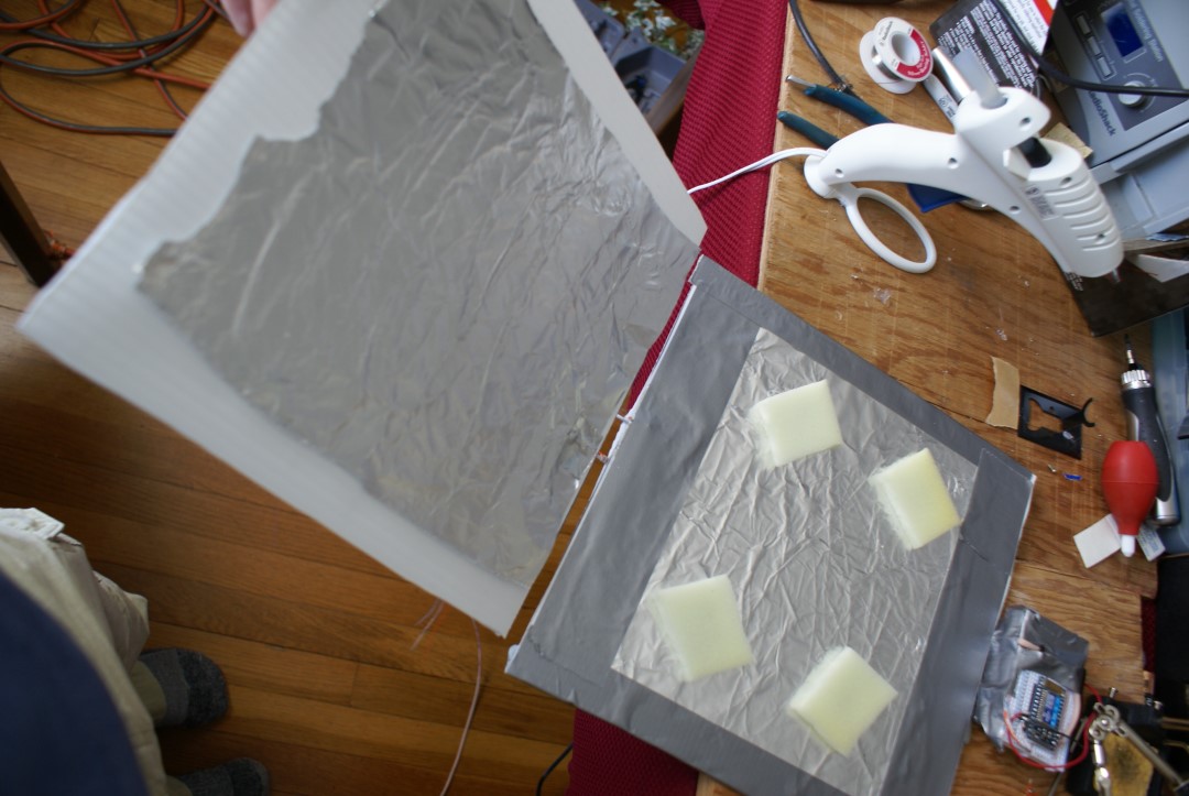
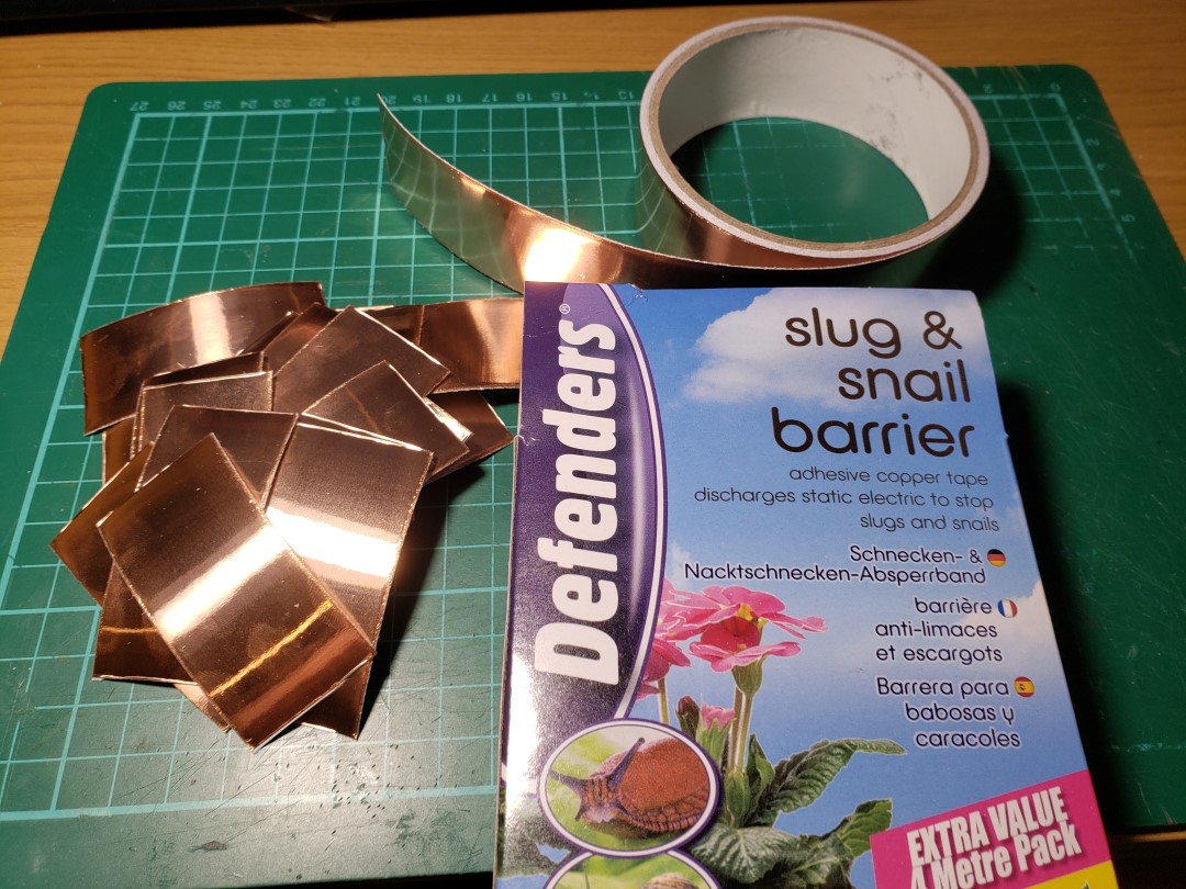
My first prototype consisted of two 3D printed plates with a sort of guide rail setup to make the plates stay on top of one another and not drift apart horizontally (not really needed since the panel would be constrained anyway by the frame). This was really thin as I only had 6 or 7mm of vertical space available at the time since I was using thicker 15mm plywood sheeting for the panels instead of the final 10mm acrylic ones. Each half was covered in copper tape, which is great for conductivity, with some of it sticking out so I could solder the wires to it. That tape is surprisingly cheap for its quality and usefulness, you can find a 4m roll of it for around €4-5, which is enough to build at least 40 of my sensors, enough for two full pads. Like Nguyen, I used two pieces of foam to bridge the plates, which worked great at first. After a few hours playing with the pad prototype, the arrows were starting to activate on their own, and sometimes remain pressed without someone stepping on them. I found out that the foam was damaged from permanent compression, and so I had to replace it. I did that a few times for each sensor initially, while I was looking for a better foam, or solution.
After I got the first acrylic panel, I “gained” some extra 5mm of vertical space to add to the sensors, so I immediately used that to make them thicker and stronger, and also to improve the “guide rail” system I had. I made it so I could clip the top part into the bottom one and have them permanently joined, separated by the same foam as before. I also made a through hole on the bottom part to pass one of the wires to the other side. This made the wiring a bit tidier, preventing the wire from moving too much and potentially getting caught between the sensor and the arrow panel, which would eventually destroy it. This still suffered from the damaged foam issue as before, but it was a bit less severe, as I used a slightly larger piece of foam. On the other hand, the larger foam made the sensor less sensitive, so the player had to step harder on the pad, which was not ideal.
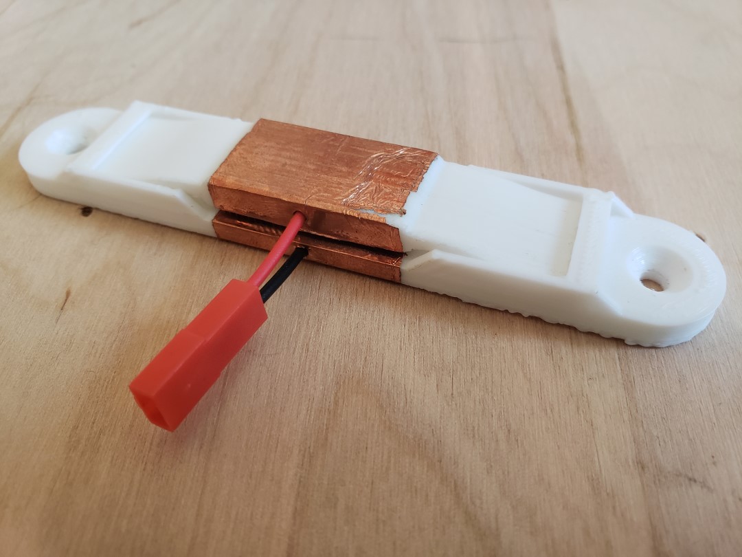
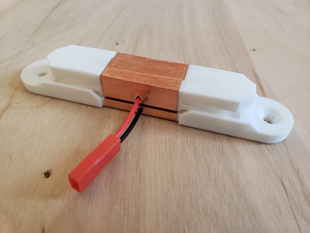
Then, suddenly, out of nowhere, as I was doing some mundane thing like using one of those food bag clips or whatever, I noticed that I could use the plastic’s deformation properties to work as the spring in my sensor. Instead of using a foam, I could use the sensor body itself as the spring. I quickly sketched up some ideas on paper then moved to Fusion360 to make some prototypes. After printing 3 or 4 similar models of just the spring element so I could find the best balance between size, movement, and sensitivity (pressure needed to fully depress it), I then printed some prototypes of full sensor units, and they seemed to work very well. The wires this time both go through the body, placing them firmly in place. This also helps to avoid breaking the solder due to fatigue from constant wire bending.
My biggest concern at this point was the strength of the plastic to keep its shape and not succumb to either fatigue or deformation (creep), the latter being a very real concern especialy for PLA 3D printed models, which is why people tend to use stronger plastics such as Nylon for parts that need to work under mechanical load. I didn’t have nylon nor had any intention of buying it, as it’s already expensive enough, even more so at the start (and during) the COVID-19 pandemic, which is when I had the idea, so I printed everything in PLA and hoped for the best. It’s been over 2 months now since I started using this new sensor design and it’s going as strong as ever, no sign of degradation so far. Of course it’s still too soon to tell if this is actually good enough on the long run, especially as I only play around 1-2 hours each session, and about 3-4 sessions a week. Ps: writing this just gave me an idea of integrating a keylogger in the Arduino code, to keep a log of how many presses each arrow takes, so I can then use to measure the longevity of the sensors and/or frame. I’ll talk more about this on the last post.
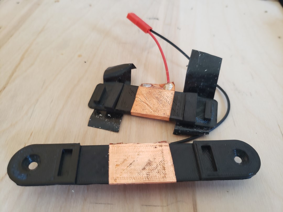
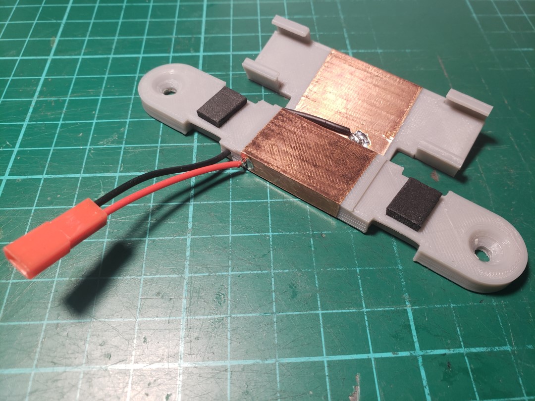
Finally, the last big change to the sensor design was the addition of some extensions on the top half. I managed to do this after I “gained” another 5mm due to the switch from wood to plastic arrow frame. The reason why I did this is because the first “all-plastic” design had a major flaw, in that the contact area between the sensor and the arrow panel was too small, creating much more friction on the acrylic panel, eroding away the copper on the sensor, and ruining the arrow’s noteskins (I forgot to take a picture of it, but the prototype acrylic panel had huge holes on the noteskins just above the 4 sensors). These extensions, which I call “wings”, had a receded slot for the copper to go through to avoid it being eroded away. This recession is only 0.2mm high, and this erosion is purely cosmetic, it does not affect the functionality of the sensor at all, since what matters is the underside of the top sensor plate.
The final measurements of the sensor are:
- Length: 115mm
- Width: 20mm at the base, 16.8mm at the top
- Height: 15mm
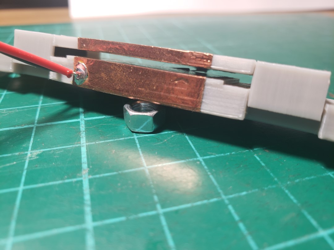
- Vertical travel (air gap): 1.5mm
- Copper contact length: 30mm (copper tape width)
- M3 screw holes separation: 98mm (don’t remember how this ended up with this odd value)
Building a sensor unit
The following tools and materials are needed to build one of the sensors:
- 3D printed sensor body
- Copper tape
- JST connector (you can buy pre-crimped connectors)
- Electrical wire (should be between 24-30AWG, maybe 22AWG will fit, YMMV)
- Solder
- Wire cutter, stripper, and crimper (crimper not needed if you get pre-crimped connectors+cables)
- Solder iron
- Pliers
- Metal file or sandpaper
Step 1: Print and clean the 3D printed parts
The 3D printed parts can be found here in Thingiverse or in PrusaPrinters. The best way to slice them to print is to orient the top half sideways, so it prints with its side on the build plate, and the bottom half on the default orientation, with the bottom on the build plate. Doing so eliminates the need for any support, and while the bottom half does have some overhangs
After printing them, use a file or just sandpaper to smooth the rough surfaces. The main surfaces that need treatment are the tips of the springs, the top surface of the wings at the top and both surfaces that will contact each other. You can position the two halves as if they’re assembled to get a better idea of which areas need more attention. There’s no need to sand down the walls to erase the layer lines, as they won’t be in contact with anything anyway. Don’t join the two pieces yet. Before proceeding to the next step, take the wire and slide it through the holes, to make sure they can get to the other side. If they’re stuck, you can use a 1.5 or 2.0mm drillbit to enlarge the hole a bit, but be careful to not enlarge it too much and end up breaking the part in half.
Step 2: Cut and apply the copper tape
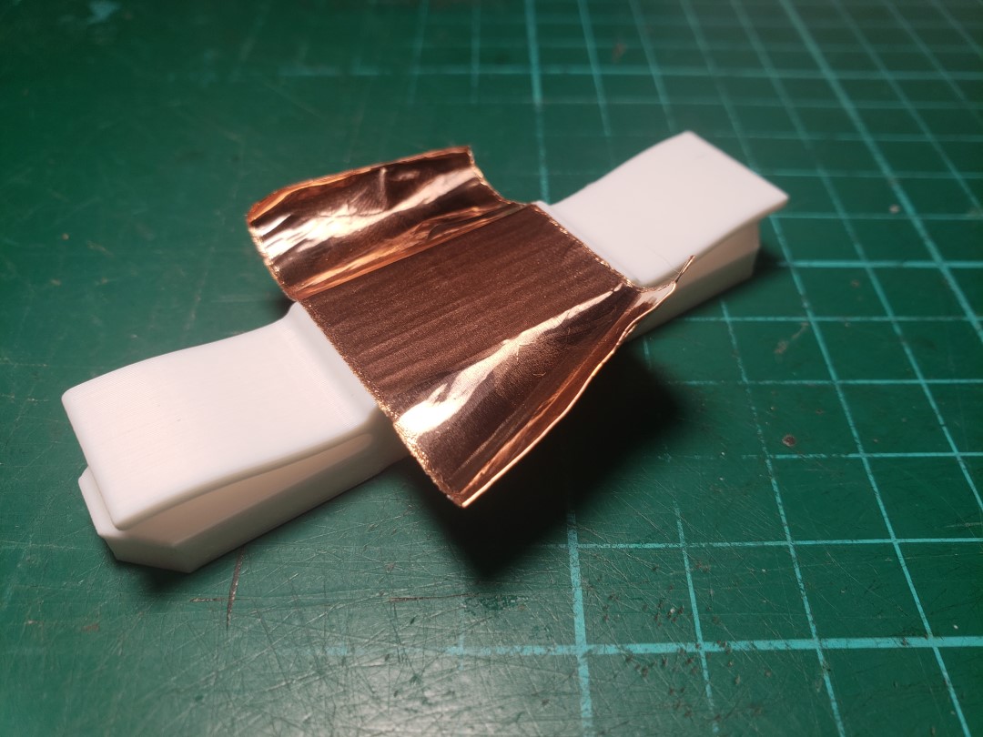
The bottom half is smaller, thus it needs less copper than the top half. I used a strip of 5cm for the bottom and 6cm for the top. This ensures that you end up with an overlap of the tape at the top, making a full loop of copper. This is not needed though, as I did it mainly for looks. Actually, if you do this with the 4m roll I mentioned before, you will not have enough tape to make 40 sensors, as you’d only have 10cm for each, and you’d be using 11cm here. If you’re planning on building two of these, you can instead use just 4.5cm for the bottom and either 5 or 5.5cm for the top half.
To apply it, remove the protective film and place it centered on the contact side of the plate, like in the picture below. Then gently wrap it around the edges. With a pointy object, pierce the copper tape where the holes are, so you can slide the cables back in later.
Step 3: Join the two halves together
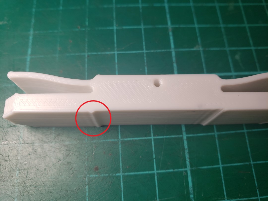
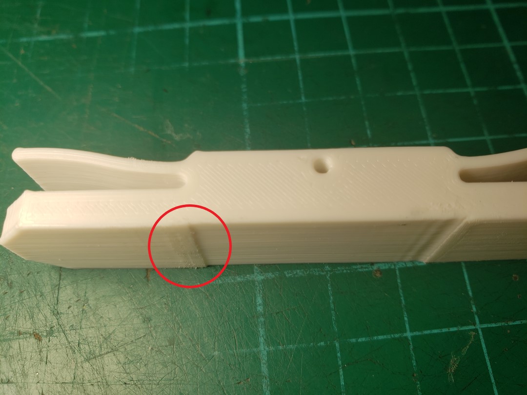
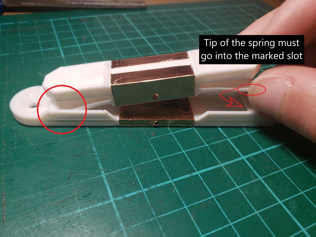
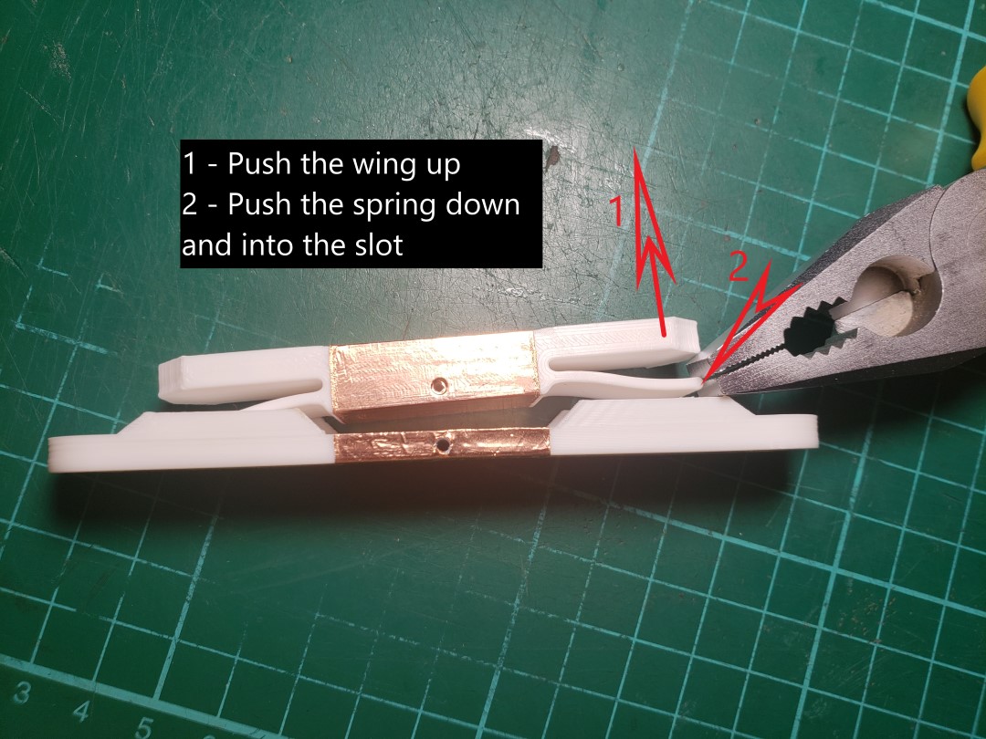
After applying the copper tape, the halves are ready to be permanently assembled. Position one end of the spring into the opening on the bottom half, and with the help of a plier or any other tool you find relevant, gently bend it so you can slide the other half in. This is tricky at first, but easy once you get the hang of it. The secret is to push the “wings” up with your fingers while pushing down the spring with a plier to get it to enter its slot.
Step 4: Position and solder the cable
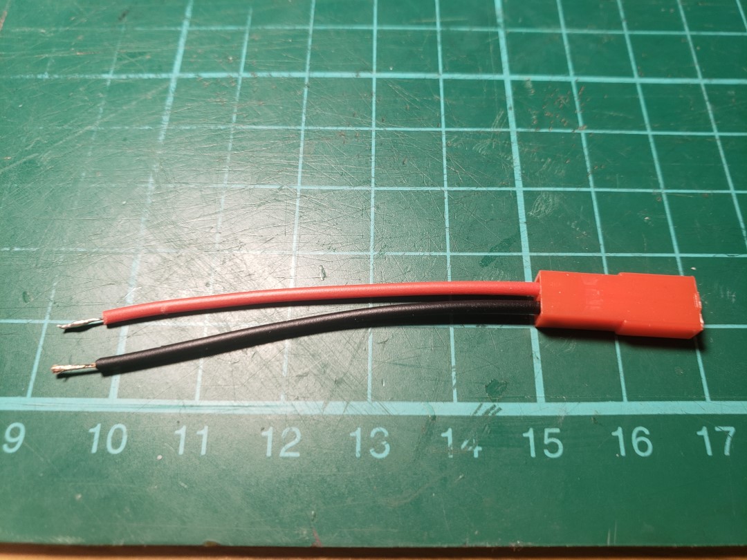
Before soldering anything, the wires needs to be cut, stripped and crimped to the connector, if it’s not already. I’ve bought some pre-crimped JST RCY connectors, so I’m not doing that part. I cut my wires to be 60mm long, which is enough to cover the roughly 20mm width of the sensor, give a 35mm extension from it, and some extra 5mm to solder to the sensor. Usually those pre-crimped wires come with their other ends already stripped and tinned (with solder on the tips), so you could just skip this part altogether and end up with a longer cable, it’s not a big issue.
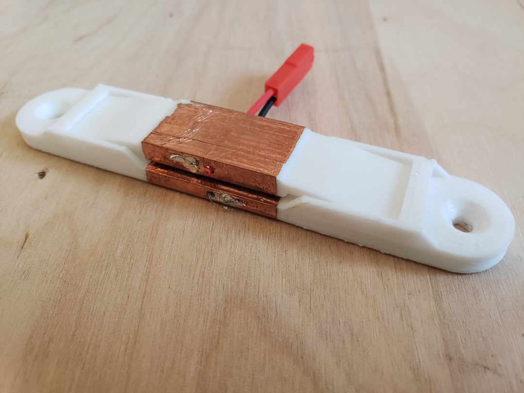
When soldering stuff, I personally like to tin (apply a thin layer of solder) both parts before joining them. This ensures the flux has enough surface area and time to work on all parts and helps to get a good solder on the end. So for the sensors, I first apply a good amount of solder to each half before even inserting the wires. Then I insert the wires, bend their tips and apply more solder to basically cover them in solder.
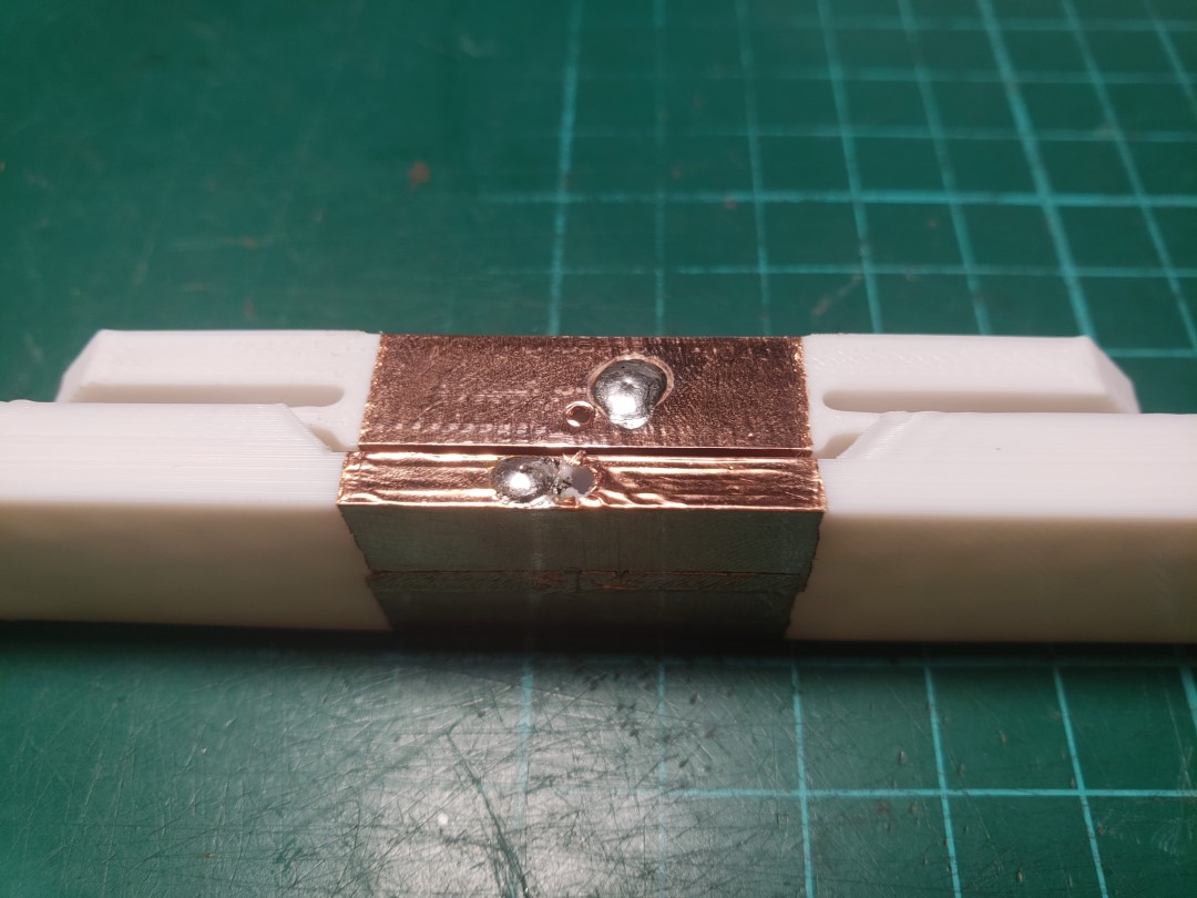
The copper is a very good thermal conductor, which means that the solder will harden pretty damn fast when you remove the iron tip. This is actually good, as directly below it we have (in my case) PLA plastic, which starts to soften at just 60ºC, way below even the temperature of boiling water, let alone molten solder. The copper helps protect the plastic, but it’s not a miraculous thermal-protecting material, so you need to be relatively quick when doing this. Keeping the solder hot for too long may soften the plastic enough to deform the contact area, potentially ruining the sensor.
…and that’s it! The sensor unit should now be ready. The pad uses 4 units for each arrow panel, so 5 arrows means there are 20 sensors per pad.