Guide on how I made the electronics of my DIY PIU pad, its constraints, pitfalls and how to wire it up.
This is the fourth post in a five part series detailing my process of building a DIY Pump it Up pad. If you don’t know what this is about, check out my project summary here. You can also jump to any part of the series:
- Part 1 - Frame Build and BOM
- Part 2 - Arrow Panels
- Part 3 - Pad Sensors
- Part 4 - LEDs and Electronics
- Part 5 - Arduino Programming
Electronics Overview
This pad was designed to be plugged to a computer and used with one of the available PIU emulators out there, such as StepF2 and StepP1. It’s not meant to replicate or emulate the original Andamiro pads, because it doesn’t have the necessary interface chips that would allow that. Instead, it acts as a general plug-and-play game controller that any modern PC can work with.
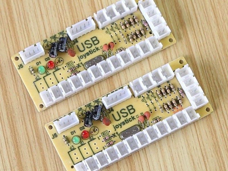
In order to make a PC understand the pad and use its arrows as input buttons, a number of alternative methods can be used. The simplest of all is to take an existing game controller or keyboard, disassemble and wire it to the sensors. A keyboard doesn’t work very well so I don’t recommend it, because keyboards usually take some “shortcuts” with its wiring to make them cheaper, and because of that they usually don’t support having more than 2 or 3 keys pressed at the same time, except for the modifier keys (ctrl, shift, alt). One could also use a generic arcade control board such as one of these, which probably works well, but I don’t know if they support debouncing, which is important and will be explained better in the next post. This series explain how to setup the pad with Arduino Leonardo, so I won’t cover these other interface methods.
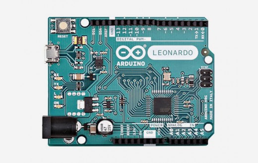
In my case, I’ve decided to use an Arduino so I would also be able to drive the LEDs and have custom code running, which allows me to tune in the sensors, and mitigate issues like input debouncing. Plus, as a programmer, this was the fun option. Not all Arduinos are the same though. In fact, only a few of them are able to do what I needed natively. There’s something called a HID (Human Interface Device), more specifically USB-HID which is a sort of specification for USB devices that are meant to be used as an input device (a HID), such as mice, keyboards or game controllers. The Arduino Leonardo is one of such versions that supports HID emulation, so I got one of these.
Basic Wiring
If you’re building a non-LED pad, all you really need apart from the sensors and the Arduino are wires. For simplicity sake, I’m going to call the sensor’s bottom side Ground (black), and the top half Signal (red). It doesn’t really matter if these are inverted, as these sensors have no polarity. As said before, this sensor design acts like a push button. Usually the push button’s signal wire also has to be connected to ground using a high valued resistor. This is called a pullup resistor, and is needed so that the button is always in a known state. This is not needed in this instance though, because Arduino boards do this very nice thing where they already have an internal pullup resistor, so that’s one source of complexity gone.
For each arrow, all four sensors should be connected to one another, in a way so that all Ground wires are connected to each other and all Signal wires are connected to each other, but of course Signal and Ground are still separate. The joined Ground wire goes to the GND pin of the Arduino and the Signal wire goes to one of the digital input pins. Which pin you connect them to doesn’t matter as this will be configured later in the coding. Note that all five arrows have a common Ground (all of them goes to the same GND pin), but they should go to different Signal pins, so 5 digital pins are needed. And that’s it for the wiring, now you just need to connect the Arduino to the PC with a USB cable and write and upload the code.
A tip I have to make the wiring look better is to measure the wire length before and cut just the amount you need plus around 5 to 10% extra to make sure the wire gets where it should and there’s not a lot of extra wire all over the place. Also, if possible, use connectors, like in the photo below, as they help with maintenance. If one of the sensors stop working, or the cable snaps, you only need to disconnect the cable and change it, instead of having to un-solder and re-solder it back in place. Shrink tubing should always be used too, it helps avoid short circuits and also help to give the project a more professional looking finish.
LED Wiring
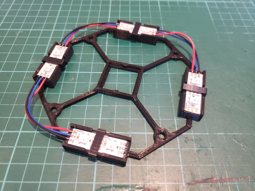
LED lighting makes the electronics a little trickier, but again, it’s mostly just wiring. For each arrow I’ve used 8 LEDs from a WS2812B LED strip, cut into four pieces of 2 LEDs each. These were assembled with the help of a 3D printed support thingy, which I’ll call the “LED module”. The LEDs goes around its centre in a square configuration, to help spread the light a little better. In the centre of the module there’s a piece of stripboard, aka veroboard, where I’ve soldered a JST plug for a four-wire cable. A stripboard of a piece of circuit board that has a grid of holes, much like a breadboard, and some of these holes are connected in a strip pattern. It’s essentially a breadboard that you can solder into. The plug is there to make the circuitry more modular, making it easier to service and/or disassemble if necessary, but that’s not really required. The LED module has some little extra clips that hold down the pieces of LED strips. That, in conjunction with the soldered wires make the module a decently solid build. While there’s nothing properly glueing the LEDs to the plastic module, there’s little play in it.
Please note that depending on the the LED strip model, it might be directional, so you have to look for each piece’s input and output sides. On the WS2812B you can notice that there’s a little arrow on them that shows the strip direction. It also has a “Din” label on its input side and a “D0” label on its output side.
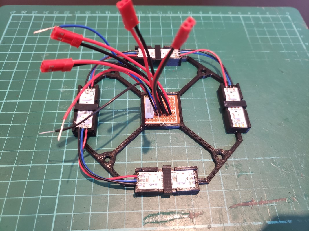
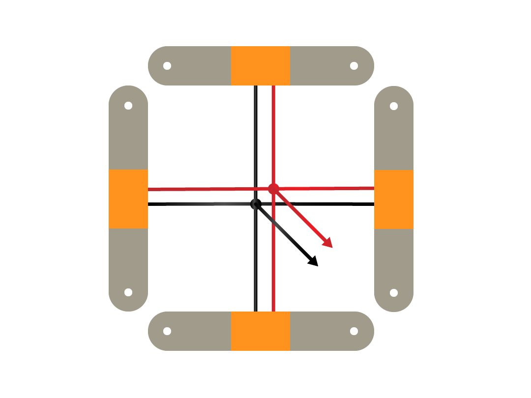
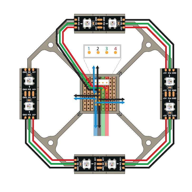
Since I was already making a board to put the LED wires in it, I also used the board to plug in the sensors. This allowed me to use the same Ground wire for both the sensors and LEDs, and also only required a single 4-core cable (a cable with 4 inner wires) to run from each arrow back to the Arduino. Here’s what each wire represents in the diagram below:
- Sensor Signal wire (goes to the top half of the sensors)
- LEDs and Sensor Ground wire (goes to the base of the sensors and GND pin on the LED strip)
- LED Control wire (goes to the Din pin of the LED strip, more on this in the next post)
- LED Vcc wire (provides 5v power to the LED strip)
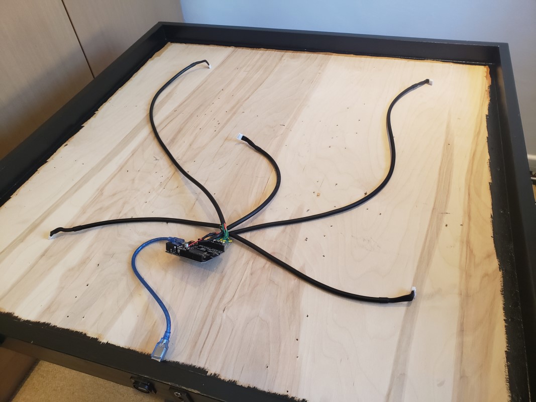
With the wiring on each individual arrow done, all that’s left is to assemble the wires that run between the arrows and the Arduino. For this I used a 4-core cable, cutting it to a length that’s always a bit larger than it needs to be, to leave some slack in case something is measured wrong. To build each wire I had to cut it to length, strip, tin and solder its leads to the appropriate connectors. I’ll not go further into this as there are many guides on the internet on how to do that. In the end, I had my finished wiring harness for the pad, and was ready to hook it all up and test it.
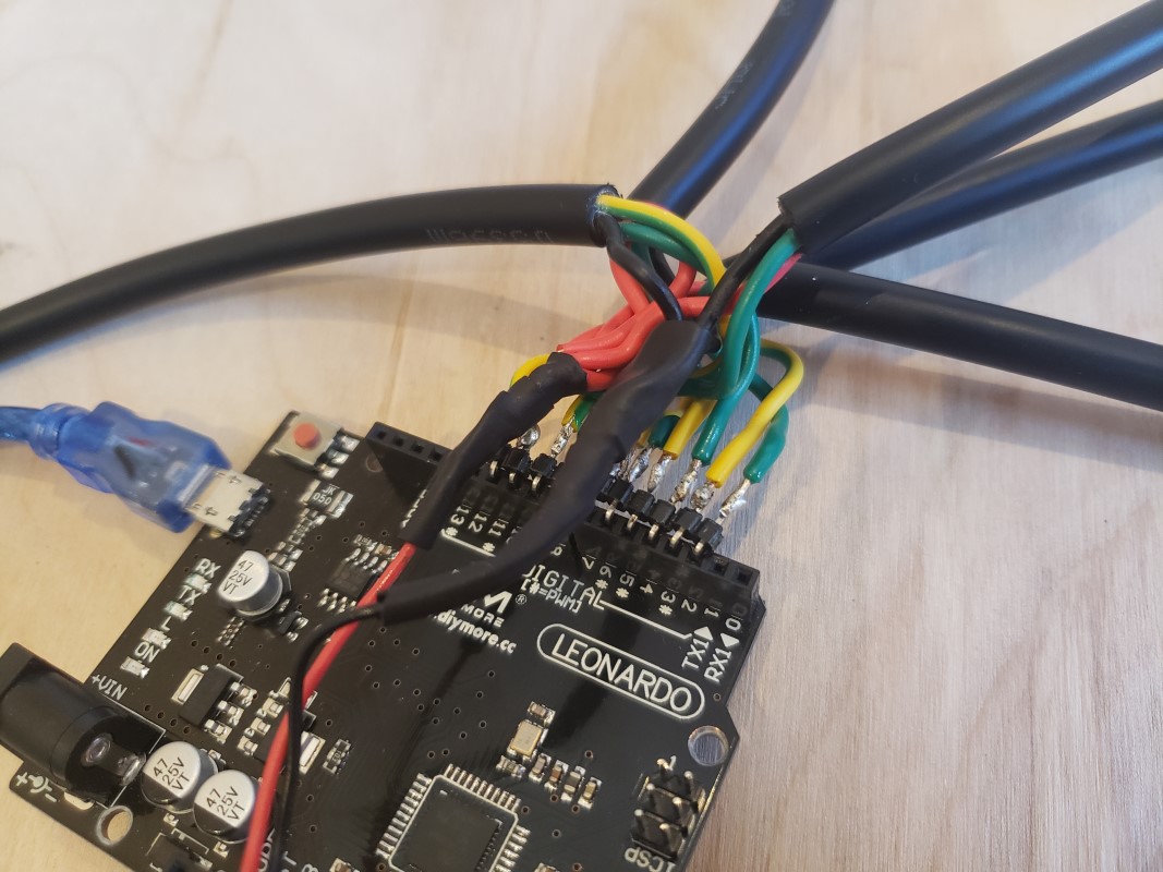
On the pictures below you can see the wiring harness and the connection coming to the Arduino. It’s a bit of a mess, but the green wires are for sensors and the yellow/green wires are for LED control, and all five cables converge to the same GND and 5v Vcc pins.
LED power consumption
The use of LEDs can cause a somewhat unexpected problem for the pad: lack of power. According to Wikipedia, a USB 2.0 will allow up to 500mA of current to be drawn, while a USB 3.0 port will go up to 900mA. This is not a universal limit though, as some motherboards might offer more power in ports that are meant to be used to charge USB devices (usually they’ll have a lighting icon next to it). But why is this important? Because RGB LEDs are actually made of three or four separate little LEDs, one red, one green, one blue and sometimes a white one too. Each one of these can draw usually up to 10-20mA, so if you consider that each LED can draw a maximum of 60mA, this pad has 8 LEDs per arrow and 5 arrows, drawing a total of 2,400mA, which is over 3 times the USB 3.0 port limit, oops!
There are a number of strategies to avoid this issue. You can simply use less LEDs per arrow, use the LEDs with a lower brightness setting, or even plug in an external power source along with the USB connection. I initially chose the latter, plug in an external power source, which you can see in the pad photos, there’s an extra, unused round power port there. I didn’t have the power source though, so I ordered one from China. It took so long to arrive that I decided to start testing the LEDs, as I already had everything else. With this testing I found out that I didn’t in fact need this power source. I just lowered the brightness and ended up with a maximum power consumption of just below 1100mA. You’ll notice that this is still higher than the USB 3.0 limit, but even with all LEDs lit up, they still kept to the same brightness without issue, so I assume my USB 3.0 port is one of those that can offer a higher current.
WARNING: Driving the pad with a current that’s above your USB port’s rated limit may damage or even fry the PC motherboard after some time, so be warned. Luckly, this high current usage will only happen when all five arrows are pressed at the same time, which is very, very rare in normal gameplay, unless you’re trying to light them up on purpose. Therefore, this shouldn’t pose a huge issue, but it’s something to keep in mind. YMMV.
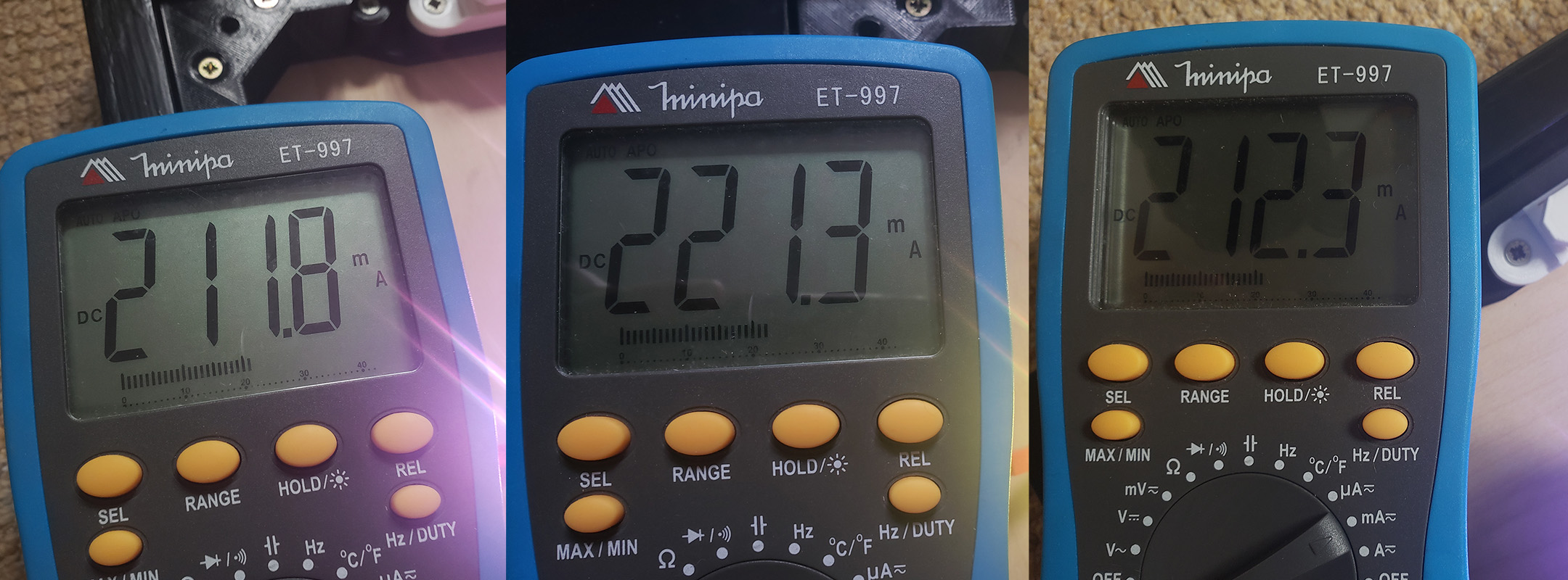
Also, if you’re doing what I did and setting the LED colour to different colours depending on the arrow (red for top arrows and so on), note that each colour draws a different amount of current, so I recommend, if possible, to use a multimeter to measure the current draw to make sure it’ll be safe. My readings are as follows:
- Red: 212mA (avg 26.5mA per LED)
- Yellow: 221mA (avg 27.65mA per LED)
- Blue: 212mA (avg 26.5mA per LED)
The pad has 2 red arrows, 2 blue arrows and 1 yellow “arrow”, adding up to a nominal total draw of 1069mA. The actual power draw of the whole pad (not only the LEDs) was then measured with a multimeter, using two different power sources: a standard phone charger, which should be able to supply up to 2A (2000mA), and the intended USB 3.0 port on my laptop. These are the readings I got from each:
- Phone charger: 1030mA
- USB 3.0: 970mA
This shows that the USB port is indeed limiting the amount of power that the pad receives, but that’s still a tad above the theoretical limit of the port. I say theoretical as I’m not sure on the specification for that specific port on my laptop. Given that the power is being limited, I think it should be safe enough to run the pad with this configuration, but again, please keep that limit in mind. The next post will explain how to configure the LED colours and brightness levels to keep current draw in check.
Future improvements
The pad works great the way it turned out, but there are a few things that I’m not 100% satisfied with:
- The wiring is a mess, the connections on the Arduino board are confusing and probably very fragile. Also, the five big harness cables are directly soldered to one another. Ideally the Arduino would be soldered to another board, maybe a stripboard, and that would contain connectors to all five arrows. This would make everything cleaner, more robust and more modular, allowing for easier maintenance. The sensor connectors are also not ideal, they use RCY JST connectors, which can’t be soldered to a PCB, so they just float around and the LED module has random wires coming off of it, again, making it more confusing.
- Each arrow has four sensors, but they’re all connected to each other. This means that I can’t detect if I’m pressing the left or the right sensor, for instance. If one of the sensors stop working, I might not notice it immediately, leading to steps missed in a song and some frustration. To get around this, I could just run more wires to the Arduino and have a digital pin assigned to each different sensor. This doesn’t work, however, because with the LEDs, there are simply not enough pins on the Arduino to do that. One possible solution is to design a custom PCB circuit, and use a chip such as a 74HC4051 demultiplexer. This would allow Arduino to use an extra two address pins to choose between the sensors to decide which sensor it will read next. The cost of this is added complexity both electronically and on the code, but it would give better debugging capabilities to the pad.
- Use custom-built boards for the arrows and also for the main Arduino core. Using stripboards like I am for the LED module is great because it’s quick and cheap, but the soldering can get a bit messy, and it just doesn’t look professional.
These are just nice things that I personally would like to implement, none are really necessary, I will try to implement them in my second pad, if and when I build it (I always wanted to play double songs), and write a new post if I succeed.